

Modbus exception codes: what 01 to 0B mean and how to fix each
Every exception code in the Modbus specification: what the server is telling you, the usual cause on site and what to change, with real frames.
By the LADX engineering team
Short answer
A Modbus exception is a reply carrying your function code plus 0x80 and a one-byte code saying why the server refused. 01 means the function is not supported, 02 the address range does not exist, 03 a value or quantity is not allowed, 04 the device failed, 05 and 06 mean wait, and 0A and 0B are gateway faults. No reply is a timeout, not an exception.
An exception is good news of a kind. It means the request reached the device, the frame arrived intact, and the device understood it well enough to refuse. A timeout means none of that happened. Telling the two apart is the first step in every Modbus fault, and the specification is precise about which is which.
The codes and definitions here come from the MODBUS Application Protocol Specification V1.1b3, the edition the Modbus Organization publishes, with its TCP/IP and serial line implementation guides for the parts that depend on the transport. The causes and fixes are what those definitions mean on site.
Four things can happen to a request
The specification lists four outcomes for every request a client sends:
| At the server | What the client sees |
|---|---|
| Received without a communication error and handled normally | A normal response |
| Not received, because of a communication error | Nothing. The client eventually times out |
| Received with a communication error (parity, LRC, CRC) | Nothing. The client eventually times out |
| Received without a communication error but cannot be handled | An exception response |
So exceptions never come from noise, a broken wire or a wrong baud rate. Those produce silence. If your master logs exception 02, the cable got the request there and the reply back.
What an exception reply looks like
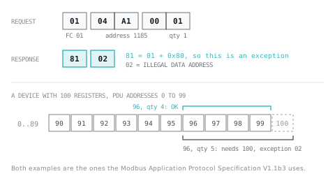
A normal reply echoes the request's function code. An exception reply sets the top bit of the function code, making it exactly 0x80 higher, and puts a single exception code in the data field. This is the specification's own example: a read of one coil at address 1185 on a device that has no such output.
Request (function 01, read coils)       Exception response
01      function code                   81      01 + 0x80
04 A1   start address 0x04A1 = 1185     02      ILLEGAL DATA ADDRESS
00 01   quantity of outputs: 1
On Modbus TCP the same PDU travels behind the 7-byte MBAP header: transaction identifier, protocol identifier (0 for Modbus), length, and unit identifier. The length counts every byte after it, unit identifier included. Taking the TCP implementation guide's example request, a read of one holding register at address 4 with unit identifier FF, the reply from a device with no register 4 would be:
Request:   00 01  00 00  00 06  FF  03  00 04  00 01
Response:  00 01  00 00  00 03  FF  83  02
           trans  proto  len    unit FC  data
The response length is 3: one byte of unit identifier and two bytes of PDU. On a serial line the PDU sits instead between the slave address and the CRC or LRC.
The exception codes
| Code and name | What the specification says | Usual cause on site | What to change |
|---|---|---|---|
| 01 ILLEGAL FUNCTION | The function code is not an allowable action for this server. It may not be implemented, or the server may be in the wrong state, for example unconfigured | A function the device does not implement, for example 16 sent to a device that only implements 06; a device still waiting for configuration | Use a function from the device manual; finish commissioning the device |
| 02 ILLEGAL DATA ADDRESS | The combination of start address and quantity is not valid for this server | The 40001 offset applied twice or not at all; a block running past the end of the map; a gap in the map | Correct the numbering; shorten or split the block |
| 03 ILLEGAL DATA VALUE | A value in the request's data field is not allowable, such as an implied length that is wrong. It specifically does not judge whether a value makes sense to the application | Quantity above the function's limit; a byte count that does not match the quantity; a coil value other than 0x0000 or 0xFF00 | Fix how the master builds the request |
| 04 SERVER DEVICE FAILURE | An unrecoverable error while the server was carrying out the action | An internal fault in the device, or in something it depends on | Device diagnostics and the vendor; check whether one register or every request fails |
| 05 ACKNOWLEDGE | Accepted, but it will take a long time; sent so the client does not time out. Specialised use with programming commands | A long programming or storage operation | Poll for completion rather than resending |
| 06 SERVER DEVICE BUSY | Busy with a long programming command; retransmit later. On TCP a server also returns it when it has no free transaction slot | Too many requests or clients at once | Back off and retry; poll less often; fewer simultaneous clients |
| 08 MEMORY PARITY ERROR | With functions 20 and 21 (file records), the extended file area failed a consistency check | A storage fault in the device | Retry; the specification says service may be needed |
| 0A GATEWAY PATH UNAVAILABLE | The gateway could not allocate an internal path from input port to output port; usually misconfigured or overloaded | A unit identifier the gateway has no route for; an overloaded gateway | Check the gateway's routing and unit ID mapping |
| 0B GATEWAY TARGET DEVICE FAILED TO RESPOND | No response was obtained from the target device; usually it is not present on the network | Wrong serial address, mismatched baud rate or parity, wiring, or a device that is switched off | Work along the serial side of the gateway |
About 07: many vendor tables add 07, NEGATIVE ACKNOWLEDGE. It is not in the exception code table of V1.1b3, which mentions a program NAK exception only in its serial diagnostic counters and event log. If a device sends 07, its own manual defines it.
The order a server checks things
The specification's transaction diagram has the server validate in a fixed order: function code first (01), then data address (02), then data value (03), then execution (04, 05 or 06). The diagrams for the individual read and write functions put the quantity check before the address check, so an oversized request is rejected with 03 before its address is even looked at.
| Function | Quantity the specification allows | Out of range gives |
|---|---|---|
| 01 Read Coils | 1 to 2,000 | 03 |
| 02 Read Discrete Inputs | 1 to 2,000 | 03 |
| 03 Read Holding Registers | 1 to 125 | 03 |
| 04 Read Input Registers | 1 to 125 | 03 |
| 05 Write Single Coil | Value 0x0000 or 0xFF00 only | 03 |
| 15 Write Multiple Coils | 1 to 1,968, with a matching byte count | 03 |
| 16 Write Multiple Registers | 1 to 123, with a byte count of twice the quantity | 03 |
A worked example: a SCADA driver set to read 200 holding registers in one block gets 03 on every poll, because the limit for function 03 is 125. Splitting it into 125 and 75 clears the fault, as long as both blocks fall inside the device's map; if the second one runs off the end, you will meet 02 next.
02 in detail
The specification's own example is the clearest: a device with 100 registers addresses them 0 to 99 in the PDU. A request starting at 96 for 4 registers succeeds. Starting at 96 for 5 fails with 02, because it would include register 100.
On site, 02 usually has one of three causes:
- Numbering. The manual says 40001; the PDU address is 0. In the specification's words, data numbered X is addressed as X-1 in the PDU. A master that expects the manual's numbers subtracts for you; one that expects PDU addresses does not. Modbus explained covers how the two conventions collide.
- The end of the map. A block length that runs past the last register, exactly as in the example.
- Gaps. Many maps are not contiguous, and depending on the device a block read across unused addresses can be refused even though both ends exist.
Keep the register map with its numbering convention written down. The I/O list template has room for address, type and range per signal; add a column that says whether the addresses are 0-based or 1-based. PLC data types helps when the address is right but the value is not.
03 is not "value out of range"
The specification is explicit that 03 is about the structure of the request, not about whether a value makes sense: Modbus has no idea what any register means. So 03 points at how the master built the frame: a quantity over the function's limit, a byte count on function 15 or 16 that does not match the quantity, or a coil write on function 05 with a value other than 0x0000 or 0xFF00.
If a device returns 03 for a well-formed write of a setpoint it considers out of range, that is the device's own convention rather than the specification's, and its manual will say so.
Gateways: 0A and 0B
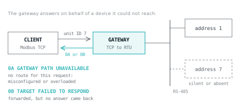
On Modbus TCP the server is addressed by its IP address, and the unit identifier in the MBAP header exists for reaching devices behind a gateway: the IP address selects the gateway and the unit identifier carries the serial slave address. For a device directly on TCP the implementation guide recommends 0xFF as the unit identifier, and notes that 0 is also accepted.
Exceptions 0A and 0B are the gateway answering on behalf of a device it could not reach. 0A means it could not set up a path from its input port to an output port, usually because no route is configured for that unit identifier or because it is overloaded. 0B means it passed the request on and nothing came back.
Serial addresses run from 1 to 247; 0 is the broadcast address and 248 to 255 are reserved. A broadcast never gets a reply. So fixing 0B is serial-line work: compare the device's address with the unit identifier, then its baud rate, parity and stop bits against the gateway port, then the wiring and termination. If other devices on the same line answer and one does not, the fault is that device's address, settings or drop cable.
No reply is not an exception
On a serial line the master starts a response timeout after each request it addresses to a single slave. If nothing valid arrives before it expires, the master reports an error and may retry. The serial guide gives a typical response timeout of one to several seconds at 9600 bit/s. Frames that fail the parity or CRC check are not answered, and broadcasts are never answered.
| What you see | What it means | First check |
|---|---|---|
| A reply with the function code plus 0x80 | The device received the request and refused it | The exception code, then the request |
| Timeout on every request | Nothing is getting through, or nothing is coming back | Address, baud rate, parity, wiring; on TCP the IP address, port and unit ID |
| Timeouts on some requests | A marginal line, or a device slower than the timeout | Termination and noise; the timeout against the device's response time |
| Exception 0B from a gateway | The gateway got through to the serial side but not to the device | The serial side, as above |
How clients report exceptions
Clients rarely show the raw byte. Siemens' MB_CLIENT, for example, translates the server's exception into its STATUS word: 01 appears as 8381, 02 as 8383, and 03 as 8382, 8384 or 8385 depending on the function. MB_CLIENT in TIA Portal has the full table. Whatever the client, find its mapping in the manual before deciding the device is at fault.
A troubleshooting order
- Decide whether you have an exception or a timeout. Everything else follows from that.
- For a timeout, work through the physical and addressing layers, using a troubleshooting method rather than changing several settings at once.
- For 01, compare the function code with the device's list of supported functions.
- For 02, check the numbering convention, then the block length against the end of the map.
- For 03, check the quantity against the limits above and how the master builds the frame.
- For 04, 05 or 06, look at the device itself: its diagnostics, its load and how often it is polled.
- For 0A or 0B, check the gateway's routing first, then the serial side.
- Write the result down. A Modbus communications test belongs on the commissioning checklist: one read and one write per device, plus the exception or timeout you expect when the device is disconnected, so the next fault starts from a known baseline.
Sources and further reading
- Modbus Organization: MODBUS Application Protocol Specification V1.1b3 (section 7, exception responses)modbus.org
- Modbus Organization: MODBUS Messaging on TCP/IP Implementation Guide V1.0b (MBAP header, unit identifier, gateways)modbus.org
- Modbus Organization: MODBUS over Serial Line Specification and Implementation Guide V1.02 (addresses, broadcast, response timeout)modbus.org
- Siemens TIA Portal V21: MB_CLIENT parameter STATUS, mapping server exceptions to STATUS codesdocs.tia.siemens.cloud
Common questions
- What does 'exception response from slave device' mean?
- It means the device received your request without a transmission error but would not carry it out, so it replied with the function code plus 0x80 and an exception code. The code gives the reason: an unsupported function, an address range that does not exist, a malformed value or quantity, a device fault, or a gateway problem.
- Why do I get exception 02 when the register exists?
- Because the check covers the whole range, not just the start address. Reading five registers from 96 on a device with registers 0 to 99 fails although 96 exists. Then check numbering: a manual's 40001 is PDU address 0, so a master that sends the manual's number unchanged is one register out.
- What is Modbus exception code 11?
- Exception 11 in decimal is 0B in hex: GATEWAY TARGET DEVICE FAILED TO RESPOND. A gateway forwarded your request and the device behind it never answered, which the specification says usually means the device is not present. Check its serial address against the unit identifier, then its baud rate, parity and wiring. Exception 10 is 0A.
- Is a Modbus timeout the same as an exception?
- No. An exception is a reply: the device heard you and refused. A timeout is the absence of any reply, which the specification says happens when the request never arrives or arrives with a parity, LRC or CRC error. Timeouts point to wiring, addressing, settings or the network; exceptions point at the request itself.
- Does Modbus have an exception code 07?
- Not in the table of the V1.1b3 specification, which lists 01 to 06, 08, 0A and 0B. Code 07, Negative Acknowledge, appears in older references and in many vendor tables, and V1.1b3 still counts program NAK exceptions in its serial diagnostics, so some devices may send it. Their manuals define what it means.
Keep reading
- Networking
Modbus, still everywhere after forty years
The simplest industrial protocol, why it survives, and the three things that catch people out.
- Networking
MB_CLIENT in TIA Portal: Modbus TCP setup and STATUS codes
Set up MB_CLIENT on an S7-1200 or S7-1500: the connection, MB_MODE and addressing, polling several blocks, and what every STATUS code means and how to fix it.
- Networking
Unified namespace: the idea, and what it does not solve
One broker, one hierarchy, every system publishing and subscribing. Why it beats point to point integration, and the three things it does not fix.