

Traffic light ladder logic: a PLC program you can run and test
A four-way junction in 25 rungs: a step machine with amber and all-red clearance, a flash mode, a conflict check, and a test table for every step.
By the LADX engineering team
Short answer
Build the traffic light as a step machine: an integer holds the current step, one timer measures how long the step has lasted, and a separate block of rungs turns the step number into lamps. Every green is followed by amber and then an all-red clearance before the other road gets green, and a conflict check forces flashing red if two greens ever appear.
The traffic light is the classic first sequencing exercise because it looks trivial and is not. Most published solutions chain timers so that each one starts the next. That works until you need a flash mode, a fault, or one more step, and then every rung after the change needs editing.
The program here is built as a step machine, the same structure as any machine sequence, and runs on the free ladder simulator using only its 23 instructions. Every rung is below, followed by a table of what each lamp should do at every second, so you can prove it works rather than compare it with a picture.
This is a training exercise. Real junctions are run by dedicated traffic signal controllers with an independent conflict monitor, and their timings are set by traffic engineers. The US Manual on Uniform Traffic Control Devices (MUTCD) is cited below for what the intervals are for, not as a design guide.
The junction and the sequence
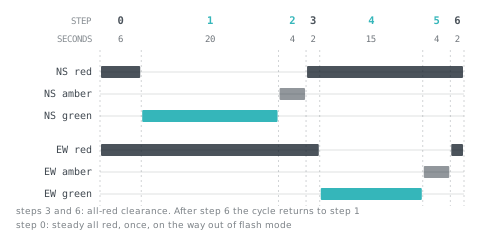
Two roads cross: north-south (NS), the main road, and east-west (EW). Opposite approaches always show the same aspect, so there are six lamp outputs, red, amber and green for each road. The cycle has seven steps.
| Step | NS | EW | Time | Purpose |
|---|---|---|---|---|
| 0 | Red | Red | 6 s | Steady all red after flash mode, once |
| 1 | Green | Red | 20 s | Main road runs |
| 2 | Amber | Red | 4 s | Change interval |
| 3 | Red | Red | 2 s | Red clearance |
| 4 | Red | Green | 15 s | Side road runs |
| 5 | Red | Amber | 4 s | Change interval |
| 6 | Red | Red | 2 s | Red clearance, then back to step 1 |
Steps 3 and 6 are the ones most classroom solutions leave out. MUTCD Section 4F.17 says the amber (yellow in US terms) change interval exists only to warn approaching traffic that its permission to proceed is ending. Its guidance is 3 to 6 s, with the longer values on faster approaches. A red clearance interval can follow, to give extra time before conflicting traffic, pedestrians included, is released, and should normally last no more than 6 s. Both durations are to come from engineering practice, not from a table like this one.
Step 0 follows Section 4G.04 for leaving flash mode when all approaches flash red: the flashing reds turn steady, for at least 6 s by its guidance, and the cycle then starts with the main road's green.
Why a step number rather than chained timers
There are three common ways to sequence lights in ladder. They all run the basic cycle, and they differ in what happens when you change it.
| Approach | How it works | Where it breaks |
|---|---|---|
| Chained timers | Each timer's done bit starts the next one; lamps come from timer bits | Adding a step means editing every rung after it, and a flash mode has to break into all of them |
| One timer and comparisons | One timer runs the whole cycle; GEQ and LES windows on its accumulator light each lamp | Times hide in compare constants that depend on each other; holding a step is awkward |
| Step number and timer | An integer says which step is active, a timer says how long it has lasted, and lamps are decoded from the step | Needs the discipline that only one place changes the step |
The step version is longer to type and much quicker to change. It is a state machine: the states are the steps, and the transitions are the timer finishing. On Rockwell controllers the other tidy option is the SQO sequencer instruction, which the LADX simulator does not have.
Tags
| Tag | Type | What it is |
|---|---|---|
| Auto_Sw | BOOL, selector | 1 runs the cycle, 0 flashes red |
| Reset_PB | BOOL, pushbutton | Clears a latched conflict fault |
| Normal | BOOL | Running the cycle with no fault |
| Fault | BOOL | Latched conflict |
| Step | INT | Current step, 0 to 6 |
| Step_Tmr | TIMER | Time spent in the current step |
| T_Lit, T_Dark | TIMER | The flasher |
| NS_Red to EW_Green | BOOL outputs | The six lamps |
| NS_Go, EW_Go | BOOL | Green or amber showing, for the conflict check |
The program, rung by rung
Mode, timing table and step timer
XIC(Auto_Sw)XIO(Fault)OTE(Normal);
XIO(Normal)MOV(0,Step);
EQU(Step,0)MOV(6000,Step_Tmr.PRE);
EQU(Step,1)MOV(20000,Step_Tmr.PRE);
EQU(Step,2)MOV(4000,Step_Tmr.PRE);
EQU(Step,3)MOV(2000,Step_Tmr.PRE);
EQU(Step,4)MOV(15000,Step_Tmr.PRE);
EQU(Step,5)MOV(4000,Step_Tmr.PRE);
EQU(Step,6)MOV(2000,Step_Tmr.PRE);
XIC(Normal)XIO(Step_Tmr.DN)TON(Step_Tmr,6000,0);
XIC(Step_Tmr.DN)ADD(Step,1,Step);
EQU(Step,7)MOV(1,Step);
[GRT(Step,6),LES(Step,0)]MOV(0,Step)RES(Step_Tmr);- Rung 1.
Normalis true when the selector says run and no fault is latched. Every other part of the program asks this one bit. - Rung 2. Outside normal running the step is held at 0, so leaving flash mode always starts with the steady all-red.
- Rungs 3 to 9 are the timing table. Each loads its step's duration, in milliseconds, into the timer's preset. To change a time, change it here and nowhere else.
- Rung 10 times the current step. The
XIO(Step_Tmr.DN)on its own done bit makes it reset itself on the scan after it finishes. - Rung 11 therefore sees the done bit for exactly one scan, so the ADD moves on by exactly one step. Leave out that
XIOand the done bit stays on: the ADD adds one every scan and the lights race through every step in a few scans. - Rung 12 wraps step 7 back to step 1, the main road's green.
- Rung 13 catches any other value, from a bad edit or a stray write, sends it to step 0 and resets the timer, so the junction goes through a full 6 s all-red rather than jumping into a green. The two outputs sit in series, which Logix ladder allows.
The flasher
XIO(T_Dark.DN)TON(T_Lit,600,0);
XIC(T_Lit.DN)TON(T_Dark,500,0);
Two timers that reset each other, the same circuit as Problem 5 in the ladder logic practice problems. A lamp examined with XIO(T_Lit.DN) is lit for 600 ms and dark for 500 ms. MUTCD Section 4G.01 sets a flash rate of 50 to 60 a minute, with the lit part between a half and two thirds of each cycle; 600 ms lit and 500 ms dark gives about 55 a minute, lit about 55 percent of the time, plus a scan per cycle.
Lamp decode
XIC(Normal)EQU(Step,1)OTE(NS_Green);
XIC(Normal)EQU(Step,2)OTE(NS_Amber);
[XIC(Normal)NEQ(Step,1)NEQ(Step,2),XIO(Normal)XIO(T_Lit.DN)]OTE(NS_Red);
XIC(Normal)EQU(Step,4)OTE(EW_Green);
XIC(Normal)EQU(Step,5)OTE(EW_Amber);
[XIC(Normal)NEQ(Step,4)NEQ(Step,5),XIO(Normal)XIO(T_Lit.DN)]OTE(EW_Red);
Each lamp has exactly one coil, and the sequence rungs above never touch a lamp. Green and amber each belong to one step. Red is written as "not green and not amber" rather than as a list of steps, so a step added later shows red unless someone decides otherwise. In flash mode the lower branch flashes both reds and every other lamp is dark, which is the red-red flashing mode that step 0 is designed to leave. MUTCD Section 4G.03 requires the green indications to be dark in flashing mode, apart from a narrow exception for single-section green arrows.
Conflict check
[XIC(NS_Green),XIC(NS_Amber)]OTE(NS_Go);
[XIC(EW_Green),XIC(EW_Amber)]OTE(EW_Go);
XIC(NS_Go)XIC(EW_Go)OTL(Fault);
XIC(Reset_PB)XIO(Auto_Sw)OTU(Fault);
If both roads ever show green or amber together, the fault latches, Normal drops on the next scan, and the junction goes to flashing red. Reset only works with the selector at flash, so a reset cannot launch straight into a cycle; turning the selector back to run then starts at step 0.
The decode cannot produce two greens, so why check? Because the check does not depend on the decode, it catches the edit that breaks it: a copied rung with the wrong step number, an output forced during testing. MUTCD Section 4G.01 requires a real signal to have a conflict monitor (malfunction management unit) able to start the flashing mode, and treats it as separate from the controller: flashing must not stop if either is removed or switched off. A check inside the same program sees the conflict only after the scan that wrote it, so the bad outputs can reach the terminals for one scan. It teaches the idea; it is not a substitute.
Test it, step by step
Set Auto_Sw to 1 and watch the lamps against this table. Each step lasts its preset plus one scan, because the timer spends a scan resetting.
| Time after Auto_Sw on | Step | NS | EW |
|---|---|---|---|
| 0 to 6 s | 0 | Red | Red |
| 6 to 26 s | 1 | Green | Red |
| 26 to 30 s | 2 | Amber | Red |
| 30 to 32 s | 3 | Red | Red |
| 32 to 47 s | 4 | Red | Green |
| 47 to 51 s | 5 | Red | Amber |
| 51 to 53 s | 6 | Red | Red |
| 53 s on | 1, and round again | Green | Red |
Then test the parts that only matter on a bad day:
- Turn
Auto_Swoff at any point. Both reds flash, everything else goes dark, andStepreads 0. Turn it on again: 6 s of steady red, then the main road's green. - Break the decode on purpose by changing the
EW_Greenrung toEQU(Step,1). At 6 s both greens light for one scan,Faultlatches and both reds flash.Reset_PBdoes nothing untilAuto_Swis off. - Write 9 into
Stepwhile the side road is green. The lights go to all red for 6 s, then the main road's green.
To watch it as a junction, place six lamps in the free HMI builder and bind them to the six outputs; it uses the ladder editor's tags directly.
Mistakes that show up in traffic light programs
- A lamp driven from several rungs. Chained-timer solutions often put
OTE(NS_Red)in each step's rung. Each OTE writes on every scan, so the last one solved wins and the red goes dark in steps where it should be lit. Recognise it by a lamp that only works in the last step that mentions it. One coil per lamp, decoded at the end, prevents it. - No clearance. Going from one road's amber straight to the other road's green looks fine in a simulator and is the gap the all-red step exists to close.
- A step that races. A transition rung that reads a done bit which stays on moves the step every scan. The lights flick through the whole cycle in a fraction of a second, or appear stuck on the last step. Rung 10's self-reset is the cure.
- Presets in seconds. Timer presets are milliseconds on Logix and in the LADX simulator. A preset of 20 gives a 20 ms green that is never seen.
- Flash mode that leaves greens lit. If the decode does not depend on
Normal, switching to flash leaves whatever was green still green alongside the flashing reds.
Variations worth trying
- The UK sequence. In the UK, red and amber show together before green. Add a short step before each green, include it in the red and amber rungs for that road, and renumber the timing table. Nothing else changes.
- A pedestrian phase. Latch a request from a push button, add a walk step after step 6 that runs only when the request is set, and unlatch the request when the walk step ends.
- Vehicle detection. Hold the main road's green until a detector on the side road has seen a vehicle, so the side road only gets green when someone is waiting. The change is to the rule that leaves step 1.
Each of these is a change to the step rules and the decode, which is the argument for building it this way. If timers are still unfamiliar, start with TON, TOF and RTO, and if the one-scan behaviour of rung 11 is surprising, read what happens in one PLC scan.
Sources and further reading
- MUTCD 11th Edition, Part 4: Highway Traffic Signals (FHWA)mutcd.fhwa.dot.gov
- Rockwell Logix 5000 Controllers General Instructions reference (1756-RM018)literature.rockwellautomation.com
- Finite-state machine (Wikipedia)en.wikipedia.org
- Traffic light (Wikipedia)en.wikipedia.org
Common questions
- How long should the amber light be in a traffic light program?
- This program uses 4 seconds. The US MUTCD gives guidance of 3 to 6 seconds for the yellow change interval, with the longer values on faster approaches, and requires the real value to come from engineering practice. Other countries have their own rules, and real junctions are timed by traffic engineers, not chosen in the PLC.
- Why does a traffic light need an all-red phase?
- Amber warns drivers that their right of way is ending, but some will still be in the junction when it ends. A short all-red step gives them time to clear before the crossing road gets green. The MUTCD describes it as the red clearance interval and gives guidance that it normally lasts no more than 6 seconds.
- Can I use the SQO sequencer instruction for a traffic light?
- On a Rockwell controller, yes. SQO steps through an array one position at a time and writes each element through a mask into a destination word, so a fixed light sequence becomes a table of output patterns. Flash modes, faults and requests are harder to add. The LADX simulator does not have SQO, so this program uses an integer step.
- How do I add a pedestrian crossing to the traffic light program?
- Latch a request from the push button with OTL, then add a walk step after the all-red step that only runs when the request is set. Decode the walk and don't-walk lamps from the step number like the others, and unlatch the request when the walk step ends. Nothing else changes.
- Are real traffic lights controlled by PLCs?
- Real signalised junctions are run by traffic signal controller units, and the MUTCD requires a conflict monitor, separate from the controller, that can put the signal into flash. The program here is a training exercise in sequencing. It teaches the step structure real sequences use, but it is not a design for a real road.
Keep reading
- Practice
PLC ladder logic practice problems with solutions you can run
Nine graded ladder logic exercises, each with a spec, a worked solution, a scan-by-scan explanation and the wrong answer most people write first.
- Practice
PLC interview questions and answers: what interviewers listen for
Twenty-five PLC interview questions grouped by level, each with a model answer, the reasoning the interviewer is listening for, and the answer that loses marks.
- Practice
Writing a machine sequence as a state machine
One integer, one rung per state, one rung per transition, and the three rules that keep it debuggable at three in the morning.