

PLC ladder logic practice problems with solutions you can run
Nine graded ladder logic exercises, each with a spec, a worked solution, a scan-by-scan explanation and the wrong answer most people write first.
By the LADX engineering team
Short answer
Practise ladder logic on small problems you can test: a seal-in, a one-button toggle, an interlock, timers, a flasher, a counter, a latched fault, hysteresis and an XOR. Write each rung yourself, run it on a simulator and check it against the stated behaviour, not against a picture. The nine problems below each give the solution and the common wrong answer.
Most ladder logic exercises online are pictures of rungs with nothing to check them against. The nine problems here work the other way round. Each one states what the machine must do, gives a solution you can build and run, explains why it works one scan at a time, and shows the wrong answer most people write first.
The wrong answers are the useful part. Each fails for a reason that also catches experienced programmers on real machines: a contact in the wrong place, an edge that was never detected, a rung that reads a bit before or after another rung writes it.
How to use these problems
Read the spec and write your own rung before reading the solution. Then build both in the free ladder editor and simulator. It runs in a browser with no account, and its 23 instructions cover everything these solutions use. It keeps an output image, gives every instruction its own edge memory and times in milliseconds, so the scan-order effects described below happen there the way they do on a controller.
Solutions are written in Rockwell-style neutral text, one line per rung. Read it left to right: XIC(Start_PB) is a normally open contact on the bit Start_PB, XIO is a normally closed one, square brackets hold parallel branches separated by commas, the instructions at the right are the outputs, and a semicolon ends the rung. Timer presets are milliseconds, so TON(Purge,5000,0) is five seconds, which is also the time base of a Logix timer.
In the tag table, give each input the device it really is. A start button is a momentary normally open pushbutton. A stop button is a momentary normally closed one, so it rests at 1. A level is an analog value on a slider. The simulator then behaves like the panel, and the seal-in in Problem 1 has a reason to exist.
| # | Problem | Instructions | The trap it tests |
|---|---|---|---|
| 1 | Start and stop with a seal-in | XIC, OTE | Where the stop contact goes |
| 2 | One button toggles a light | ONS, XIC, XIO, OTE | Edges, and rung order |
| 3 | Forward and reverse interlock | XIC, XIO, OTE | Interlocking both directions |
| 4 | Fan run-on with a purge | TON, TOF | What a timer does at power-up |
| 5 | A flashing alarm lamp | TON twice | One-scan pulses |
| 6 | Count 12 bottles, then stop | CTU, RES | Counting edges, not scans |
| 7 | Conveyor jam timeout | TON, OTL, OTU | Latching a fault |
| 8 | Tank fill with hysteresis | LES, XIC, OTE | Deadband |
| 9 | Three-way light switch | XIC, XIO | XOR built from contacts |
Problem 1: start and stop with a seal-in
Spec. A momentary start button Start_PB, wired normally open, and a momentary stop button Stop_PB, wired normally closed so it reads 1 when nobody touches it. Pressing start runs Motor, and the motor keeps running after the button is released. Pressing stop stops it. If both are pressed, stop wins.
[XIC(Start_PB),XIC(Motor)]XIC(Stop_PB)OTE(Motor);Why it works. On the scan where start is pressed, the top branch passes and the coil writes 1. On the next scan the button has been released, but the lower branch reads Motor, which this rung wrote one scan earlier, so the rung stays true. That branch is the seal-in. Pressing stop drops Stop_PB to 0, and because it sits in series after both branches, the coil writes 0 and the seal opens with it.
Common wrong answer. [XIC(Start_PB)XIC(Stop_PB),XIC(Motor)]OTE(Motor); puts the stop on the start branch only. It starts correctly, then nothing stops it, because the seal branch goes round the stop. The other classic is XIO(Stop_PB), which with a normally closed button runs the motor only while stop is held. Seal-in or latch and normally open and normally closed cover both.
Problem 2: one button toggles a light
Spec. One momentary button PB. The first press turns Light on, the second turns it off, and holding the button down changes nothing.
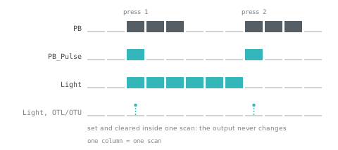
XIC(PB)ONS(PB_Store)OTE(PB_Pulse);
[XIC(PB_Pulse)XIO(Light),XIO(PB_Pulse)XIC(Light)]OTE(Light);
Why it works. The ONS passes for one scan when the button goes from off to on, then blocks until it is released and pressed again. PB_Store is its memory of the previous scan. So PB_Pulse is true for exactly one scan per press. The second rung is an exclusive OR. With no pulse, the lower branch holds Light at whatever it already was. On the pulse scan, the upper branch turns an off light on, and neither branch passes for a light that was on, so it goes off. One shots explains the instruction.
Common wrong answer.
XIC(PB)ONS(Store_1)XIO(Light)OTL(Light);
XIC(PB)ONS(Store_2)XIC(Light)OTU(Light);
Rung 1 latches the light on. Rung 2 runs later in the same scan, sees the light that was just switched on, and unlatches it. The bit is 1 only for the moment between the two rungs, so in practice the light never comes on. The drawing at the top of this page shows both versions scan by scan.
Problem 3: forward and reverse with an interlock
Spec. Buttons Fwd_PB and Rev_PB (normally open) and one Stop_PB (normally closed); outputs Fwd and Rev. The outputs must never be on together, and changing direction needs a stop first.
[XIC(Fwd_PB),XIC(Fwd)]XIC(Stop_PB)XIO(Rev)OTE(Fwd);
[XIC(Rev_PB),XIC(Rev)]XIC(Stop_PB)XIO(Fwd)OTE(Rev);
Why it works. Each rung is a seal-in with an XIO on the other direction. While Fwd is on, pressing reverse does nothing because XIO(Fwd) blocks rung 2. If both buttons are pressed on the same scan from standstill, rung 1 runs first and writes Fwd, and rung 2 already sees it. Forward wins, and rung order decided it.
Common wrong answer. Interlocking one rung only. Leave XIO(Fwd) out of rung 2, run forward, press reverse: rung 2 turns Rev on while Fwd is still on, and Fwd only drops on the next scan, when rung 1 reads Rev. For one scan both outputs are on, and on a reversing starter that means two contactors closing across the supply. Real starters are also interlocked in the wiring, so a program error or a forced output cannot close both. Motor starter logic covers the hardware side.
Problem 4: fan run-on with a purge
Spec. When the selector Heat_Req is on, Fan starts at once, and Heater may start only after the fan has run for 5 s. When Heat_Req goes off, the heater stops at once and the fan runs on for 30 s. At power-up with no request, nothing runs.
XIC(Heat_Req)TOF(Fan_RunOn,30000,0);
XIC(Fan_RunOn.DN)OTE(Fan);
XIC(Heat_Req)XIC(Fan)TON(Purge,5000,0);
XIC(Heat_Req)XIC(Purge.DN)OTE(Heater);
Why it works. A TOF sets its done bit on the scan its rung goes true and clears it only once the preset has elapsed after the rung goes false: that is a run-on. The TON starts once the fan is running and resets the moment its rung goes false, so the heater loses Purge.DN in the same scan the request drops. If the request returns during the run-on, the TOF clears its accumulator and the fan simply keeps running.
Common wrong answer. A run-on built from a TON:
XIO(Heat_Req)TON(RunOn,30000,0);
[XIC(Heat_Req),XIO(RunOn.DN)]OTE(Fan);
It works after the first heat cycle. At power-up, though, Heat_Req is off, so the timer starts timing straight away and the fan runs for 30 s that nobody asked for. A TOF does not: on a Logix controller its prescan clears the done bit and sets the accumulator to the preset, so it starts in the finished state. TON, TOF and RTO compares the three timers.
Problem 5: a flashing alarm lamp
Spec. While Alarm is on, Lamp flashes 0.5 s on and 0.5 s off, starting lit. When the alarm clears, the lamp goes out.
XIC(Alarm)XIO(T_Dark.DN)TON(T_Lit,500,0);
XIC(T_Lit.DN)TON(T_Dark,500,0);
XIC(Alarm)XIO(T_Lit.DN)OTE(Lamp);
Why it works. T_Lit times the lit half and T_Dark the dark half. When T_Dark finishes, rung 1 goes false on the next scan and resets T_Lit, which makes rung 2 false and resets T_Dark in the same scan. On the scan after that, T_Lit starts again. The lamp is lit whenever T_Lit has not finished, so it lights the moment the alarm appears. Each half lasts its preset plus about one scan, which nobody sees at 500 ms.
Common wrong answer. One timer that resets itself:
XIC(Alarm)XIO(T_Flash.DN)TON(T_Flash,500,0);
XIC(T_Flash.DN)OTE(Lamp);
The done bit is true for one scan only: the scan it finishes, before the next scan's XIO(T_Flash.DN) resets the timer. The lamp gets a pulse one scan long every 500 ms. On a controller scanning every few milliseconds that is a flicker nobody sees, and a relay output may not pull in at all. A self-resetting timer is a good one-scan clock, and the step timer in the traffic light program uses one that way, but it is not a flasher.
Problem 6: count 12 bottles, then stop
Spec. A photo-eye Bottle_PE sees each bottle. Conveyor runs while Run_Sw is on until 12 bottles have passed, then stops and lights Batch_Done. Reset_PB starts the next batch.
XIC(Bottle_PE)CTU(Bottles,12,0);
XIC(Bottles.DN)OTE(Batch_Done);
XIC(Run_Sw)XIO(Bottles.DN)OTE(Conveyor);
XIC(Reset_PB)RES(Bottles);
Why it works. A CTU adds one when its rung goes from false to true, not on every scan the rung is true, so a bottle that sits in front of the eye for a second counts once. On the scan the twelfth bottle arrives, rung 1 sets Bottles.DN and rung 3, below it, stops the conveyor in that same scan. RES clears the accumulator and the done bit. The count does not stop at 12: a bottle that coasts past the eye after the stop makes it 13, and Rockwell's own CTU example shows the accumulator carrying on past the preset.
Common wrong answer. XIC(Bottle_PE)ADD(Count,1,Count); adds one on every scan the beam is blocked. A bottle that blocks it for 200 ms on a 10 ms scan counts about 20. Use a counter, or put an ONS in front of the ADD. Counters and the reset everyone forgets goes further.
Problem 7: conveyor jam timeout
Spec. A box that blocks Box_PE for more than 5 s while Conveyor runs is a jam: stop the conveyor and latch Jam_Fault. Reset_PB clears the fault only when the eye is clear, and the conveyor must not restart by itself.
XIC(Conveyor)XIC(Box_PE)TON(Jam_Tmr,5000,0);
XIC(Jam_Tmr.DN)OTL(Jam_Fault);
XIC(Reset_PB)XIO(Box_PE)OTU(Jam_Fault);
[XIC(Start_PB),XIC(Conveyor)]XIC(Stop_PB)XIO(Jam_Fault)OTE(Conveyor);
Why it works. The timer only runs while the conveyor runs and the eye is blocked, so a box resting on a stopped belt is not a jam. When it finishes, the fault latches and rung 4 drops the conveyor in the same scan. On the next scan the timer's rung is false and the timer resets, but the latched fault stays until someone clears it. Rung 4 is a seal-in, so after the reset the conveyor stays stopped until start is pressed.
Common wrong answer. Stopping the conveyor straight from the timer, with XIO(Jam_Tmr.DN) in rung 4 and no latch. The conveyor stops, which makes the timer's rung false, which resets the timer one scan later. The evidence is gone before anyone looks, and an HMI alarm on Jam_Tmr.DN shows for one scan. A fault that stops a machine should be latched and reset on purpose.
Problem 8: tank fill with hysteresis
Spec. Level is a value from 0 to 100 percent. Pump fills the tank: start when the level falls below 20, stop when it reaches 80, and in between keep doing whatever it was doing.
[LES(Level,20),XIC(Pump)]LES(Level,80)OTE(Pump);Why it works. It is a seal-in with comparisons where the buttons were. Below 20 the top branch starts the pump. From there the pump's own contact holds it on through the band, and at 80 the series LES(Level,80) breaks the rung. On the way down the pump's contact is already open, so nothing restarts it until the level is below 20 again.
Common wrong answer. LES(Level,80)OTE(Pump); has no deadband. The pump stops at 80, the level dips to 79 with the first ripple, and the pump starts again, several times a second on a noisy signal. A latch pair, LES(Level,20)OTL(Pump); and GEQ(Level,80)OTU(Pump);, also works, with one difference at restart: on a Logix controller the prescan clears an OTE bit and leaves an OTL bit as it was, so a pump that was latched on when the controller stopped comes back on when it returns to run. See comparison instructions.
Problem 9: a three-way light switch
Spec. Two maintained switches, SW_Bottom and SW_Top, at each end of a stair. Flipping either one changes the state of Hall_Light.
[XIC(SW_Bottom)XIO(SW_Top),XIO(SW_Bottom)XIC(SW_Top)]OTE(Hall_Light);Why it works. The light is on when the switches disagree, which is exclusive OR. Flip either switch and they go from agreeing to disagreeing or back. No memory is needed, because maintained switches hold their own state; Problem 2's pushbutton does not, which is why it needs the one-shot and the feedback.
Common wrong answer. [XIC(SW_Bottom),XIC(SW_Top)]OTE(Hall_Light); is OR: once either switch is up, the other cannot turn the light off. Logic gates in ladder logic builds every gate from contacts this way.
Where to go next
The next step up is a sequence: several outputs in a fixed order, with timing, faults and a way to stop. The traffic light program is that exercise worked through in full, as a step machine with an all-red clearance and a conflict check.
Before it, make sure the scan cycle makes sense. Problems 2, 3, 5 and 7 are all about what one rung can see of another within a scan, and the Logix manual is explicit that the controller evaluates every instruction from the rung condition that precedes it. If you want to compare the simulators you could practise on, the PLC simulator comparison lists what each one models.
Sources and further reading
- Rockwell Logix 5000 Controllers Ladder Diagram programming manual (1756-PM008)literature.rockwellautomation.com
- Rockwell Logix 5000 Controllers General Instructions reference (1756-RM018)literature.rockwellautomation.com
- CODESYS Standard library: TON function blockcontent.helpme-codesys.com
- Siemens S7-1200 Programmable Controller system manualcache.industry.siemens.com
- Ladder logic (Wikipedia)en.wikipedia.org
Common questions
- How can I practise PLC programming at home without hardware?
- Use a simulator that behaves like a controller: one that keeps an output image, remembers edges per instruction and times in real milliseconds. The free LADX ladder editor at /ladder does this in a browser with no account. Write each problem from its spec first, then run it and toggle the inputs to test it.
- Do these exercises work in Siemens TIA Portal?
- The logic does. The names change: Siemens LAD uses normally open and normally closed contacts, set and reset coils, IEC timers (TP, TON, TOF, TONR) and counters (CTU, CTD, CTUD), and P_TRIG or P contacts for edges. The scan-order traps are the same on any controller that solves rungs in order.
- What should I learn after these practice problems?
- Sequences. A machine that moves through steps with timing, faults and a way to stop is where most real programs live. Build the traffic light as a step machine, then a state machine for a small process, then learn enough Structured Text to read it. Analog scaling and alarm handling come next.
- Why does my ladder logic work on paper but not in the simulator?
- Usually because the rungs on paper were read as if they all happen at once. A controller solves them in order, so a rung sees what earlier rungs wrote in this scan and what later rungs wrote in the last one. Duplicate coils, missing one-shots and latches that clear themselves all come from that.
- Are there ladder logic practice problems with solutions as a PDF?
- Most PDFs in search results are copies of copies, and a picture of a rung cannot be tested. Here every solution is written as text you can rebuild in a simulator and check against the spec, which tells you more than matching a drawing. Print the page if you want it on paper.
Keep reading
- Practice
PLC interview questions and answers: what interviewers listen for
Twenty-five PLC interview questions grouped by level, each with a model answer, the reasoning the interviewer is listening for, and the answer that loses marks.
- Practice
Traffic light ladder logic: a PLC program you can run and test
A four-way junction in 25 rungs: a step machine with amber and all-red clearance, a flash mode, a conflict check, and a test table for every step.
- Fundamentals
Logic gates in ladder logic: AND, OR, NOT, NAND, NOR, XOR, XNOR
Every logic gate as a ladder rung with its truth table, why NAND and NOR are drawn the way they are, and how XOR on bits differs from XOR on words.