

Cause and effect matrix: how to write one for control and safety
How to lay out, read and test a cause and effect matrix for interlocks and trips, including voting, latching, reset and bypass, with a worked example.
By the LADX engineering team
Short answer
A cause and effect matrix lists each trip condition as a row and each resulting action as a column, with a mark wherever a cause produces an effect. Each row also states the tag, trip setting, delay, voting and reset type. Read across a row for what one cause does, down a column for what stops one device, and test every mark at FAT.
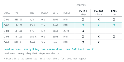
In process control and machine safety, a cause and effect matrix (C&E matrix, or C&E chart) is the grid that says which trip conditions cause which actions. It is the most testable document on most projects: every mark in it is one test at FAT, and every blank is a promise that something does not happen.
It is not the Six Sigma cause and effect matrix used to rank process inputs, and it is not a fishbone diagram. IEC 62881, the international standard for C&E matrices, says so itself: its matrices do not have the same scope as the fishbone or Ishikawa diagrams that the literature often calls cause and effect diagrams.
What the standard covers, and what it leaves out
IEC 62881:2018, Cause and effect matrix, edition 1.0, was published on 10 October 2018 by IEC technical committee 65. Its scope is narrow on purpose:
- It defines the minimum content of a C&E matrix, derived from existing design documents such as P&IDs or verbal descriptions, so that process, electrical and I&C engineers exchange the same information.
- Its introduction treats causes as signals from sensors or other sources of information, and effects as actions taken automatically by actuators (mainly valves and motors) or manually by operators, or as alarms and messages.
- It leaves the transfer from the matrix into PLC or DCS code out of scope, and it does not cover complex or sequential logic. The introduction adds that matrices are not designed to specify sequences such as batch operation.
- The introduction also names the kinds of requirement matrices help to meet, including fire and gas regulations and machinery standards such as IEC 62061.
The standard's contents list sections on layout principles, on the attributes of causes, of effects and of relations, and on marking changes and modifications. Those are the right headings to organise a matrix by, and the rest of this guide follows them.
Laying out the matrix
Causes go in rows down the left, effects in columns across the top, and the relation sits in the cell where a row meets a column. Around that grid, each row and column carries the attributes that make it unambiguous.
| Part | What goes in it | Why it matters |
|---|---|---|
| Header block | Project, document number, revision, date, approvals | The matrix is a controlled document, and the program should state which revision it implements |
| Cause reference | A unique ID: C-01, C-02 | So the code, the alarm list and the FAT all point at the same row |
| Description and tag | 'Tank level high-high', LT-101 | The tag ties the row to the P&ID and the I/O list |
| Trip setting and units | 95 %, 180 °C | Must match the range, alarm and trip schedule |
| Delay | 0 s, 2 s | A deliberate filter, stated in the design rather than added during commissioning |
| Voting | 1oo1, 2oo3 | How many of several sensors must agree |
| Reset type | Manual or automatic | Whether the effect clears by itself |
| Safety classification | SIL or other marking where a row is part of a safety function | Shows which rows must be implemented in the safety system |
| Effect columns | Device tag plus action: P-101 stop, XV-101 close | The action is part of the column, so a mark needs no explanation |
| Legend and notes | What each symbol means; general rules such as fail-safe wiring | Symbols differ between companies |
| Revision marks | A flag on every changed cell | Shows what to retest after a change |
Keep trip settings in step with the range, alarm and trip schedule, which holds each instrument's calibrated range next to every limit set against it. A trip set outside the transmitter's range never happens.
How to read it
- Across a row: everything one cause does. This is how a process engineer checks a trip and how a tester writes the FAT step for it.
- Down a column: everything that stops, closes or starts one device. This is how a maintenance technician finds out why a pump will not run.
- A blank cell is a statement. It says the cause does not produce that effect, and a good test proves the blanks as well as the marks.
- Several marks in one column are an OR. Any one of those causes produces the effect.
The symbols themselves are not fixed. A team at CERN that used matrices to specify the interlock logic of a safety instrumented system under the IEC 61511 life cycle published the semantics it adopted, adapted from oil and gas practice. It is a clear legend worth copying:
| Mark | Meaning in the CERN semantics |
|---|---|
| X | The cause, when active, triggers the effect |
| N | The cause, when inactive, triggers the effect |
| A1, A2 | The effect triggers only when all causes marked with the same A number are active together (an AND) |
| TONx | The cause must stay active for more than x seconds |
| TOFx | The effect stays active for x seconds after the cause clears |
The same paper is honest about the limits: a matrix suits stateless interlock logic, where an output depends only on the current inputs, and other methods suit other kinds of process. Whatever symbols you choose, print the legend on the sheet.
Voting: 1oo2, 2oo2 and 2oo3
When several sensors measure the same thing, the matrix must say how many have to agree before the trip happens. The notation is M out of N, written MooN.
| Voting | Trips when | Trade-off |
|---|---|---|
| 1oo1 | The single sensor trips | One failed sensor can cause a spurious trip or a missed one |
| 1oo2 | Either of two sensors trips | Favours tripping: a missed trip needs both to fail, but either can trip spuriously |
| 2oo2 | Both sensors trip | Favours running: fewer spurious trips, but one failed sensor can block the trip |
| 2oo3 | Any two of three sensors trip | One sensor can fail either way without a spurious trip or a missed one |
A 2oo3 vote is a majority function: the result is true when two or more of the three inputs are true. Write the row as the vote rather than as three separate rows, so the matrix says what the logic must do:
(* C-02: tank level high-high, LT-101A/B/C, 2oo3 *)
HH_A := LT101A > 95.0;
HH_B := LT101B > 95.0;
HH_C := LT101C > 95.0;
C02_Vote := (HH_A AND HH_B) OR (HH_A AND HH_C) OR (HH_B AND HH_C);
Then state what the vote becomes while one transmitter is faulty or out of service. Treating the failed transmitter as tripped turns 2oo3 into 1oo2 on the remaining pair; ignoring it turns it into 2oo2. Which one is right is a safety decision that belongs in the safety requirements, not a choice for the programmer, and it must be written down where the programmer will find it.
Latching, first-out and reset
A trip should latch. When the cause clears, the effect stays in place until somebody deliberately resets it; otherwise a level that dips below the trip point for a moment restarts the pump on its own. The reset type column says which rows behave that way. Automatic reset belongs to conditions where clearing really is harmless, such as a low flow that only holds a sequence.
Three rules make reset behave:
- Reset only works once the cause has cleared. Pressing reset with the level still high does nothing.
- Reset removes the trip and starts nothing. Restarting needs a separate start command through the normal permissives; seal-in and latch logic is where this usually goes wrong.
- A first-out indication records which cause tripped first. By the time anyone looks, three or four causes are usually active, and only the first explains the event.
Here is row C-02 as Rockwell neutral text, using only instructions the free ladder editor supports, so you can build it and try it:
XIC(C02_Vote)TON(C02_Dly,2000,0);
XIC(C02_Dly.DN)OTL(C02_Trip);
XIC(Reset_PB)XIO(C02_Vote)OTU(C02_Trip);
XIC(C02_Trip)EQU(FirstOut,0)MOV(2,FirstOut);
[XIC(C01_Trip),XIC(C02_Trip),XIC(C03_Trip),XIC(C04_Trip),XIC(C05_Trip)]OTE(AnyTrip);
XIC(Reset_PB)XIO(AnyTrip)MOV(0,FirstOut);
XIO(C01_Trip)XIO(C02_Trip)XIO(C03_Trip)XIO(C04_Trip)XIO(C05_Trip)OTE(P101_Permit);
The last rung is the P-101 stop column read downwards: the pump is permitted only while no cause in its column is tripped, and the permit feeds the pump's own start logic as an interlock. One subtlety of the scan cycle: if two causes latch in the same scan, the one whose first-out rung comes first in the program wins. With delays in the paths that is rare, but remember it when a first-out looks wrong.
State the fail-safe principle once in the matrix notes rather than leaving it to assumption: trip inputs wired so that a broken wire or lost supply reads as the trip state, and effects that reach their safe state when de-energised.
A worked example
A feed tank T-101 with a transfer pump P-101, an inlet valve XV-101 and an outlet valve XV-102. The matrix is small enough to read and has the features a real one needs.
| Ref | Cause | Tag | Trip | Delay | Vote | P-101 stop | XV-101 close | XV-102 close | Horn | Reset | Test |
|---|---|---|---|---|---|---|---|---|---|---|---|
| C-01 | Emergency stop | ESD-01 | n/a | 0 s | 1oo1 | X | X | X | X | Manual | FAT-SF-001 |
| C-02 | Tank level high-high | LT-101A/B/C | 95 % | 2 s | 2oo3 | X | X | X | Manual | FAT-IL-001 | |
| C-03 | Tank level low-low | LT-101A/B/C | 5 % | 5 s | 2oo3 | X | X | Auto | FAT-IL-002 | ||
| C-04 | Tank temperature high-high | TT-101A/B | 180 °C | 0 s | 1oo2 | X | X | X | X | Manual | FAT-IL-003 |
| C-05 | Remote I/O rack comms lost | RIO-1 | lost | 3 s | n/a | X | X | X | Manual | FAT-IL-004 |
Read C-02 across: high-high on two of three level transmitters for 2 s stops the pump, closes the inlet and sounds the horn, latches, and needs a manual reset. Read the XV-102 column down: the outlet closes on an emergency stop, low-low level, high-high temperature and loss of the remote I/O rack, and on nothing else.
C-05 is the row most often missing. If the rack carrying LT-101 stops communicating, the controller is blind to the level, and the matrix has to say what that means. Write communication loss, control power failure and instrument faults as causes in their own right; IEC 62881's introduction gives a trip on detection of a broken wire as an example of what a matrix can document.
Testing every mark, and every blank
Each X is one test, and each test should prove the blanks in its row as well. For C-03:
| Test | Method | Expected | Also confirm |
|---|---|---|---|
| FAT-IL-002a | Hold LT-101A and B below 5 % for 4 s | No trip | P-101 keeps running |
| FAT-IL-002b | Hold LT-101A and B below 5 % for 6 s | P-101 stops, XV-102 closes | XV-101 stays open; horn stays off |
| FAT-IL-002c | Hold only LT-101A below 5 % for 6 s | No trip | The vote needs two |
| FAT-IL-002d | Restore the level above 5 % | Trip clears by itself (automatic reset) | P-101 does not restart without a start command |
Writing the 'also confirm' column is what proves the whole matrix rather than half of it. The FAT protocol template has interlock and safety test sections laid out for exactly this, and the FAT checklist for a PLC control panel covers the rest of the test.
Where the matrix meets the safety requirements specification
On process plant, safety instrumented functions are specified under IEC 61511. Part 1 of the 2016 edition, a process sector implementation of IEC 61508:2010, gives requirements for the specification, design, installation, operation and maintenance of a safety instrumented system, and its clause 10 is the SIS safety requirements specification (SRS).
A C&E matrix is not an SRS on its own. Each safety function's specification also has to carry things a grid shows badly. The CERN paper lists the minimum for a safety instrumented function as its functionality, its target SIL and its mode of operation (low demand, high demand or continuous), and used the matrix to express the functionality part without ambiguity. In practice the matrix is often the clearest statement of the safety logic, referenced from the SRS, with a column marking which rows are SIL-rated.
Two consequences for the program:
- Rows that belong to a safety function go in the safety logic solver, not in the process PLC next to the process logic. A safety instrumented system is meant to be independent of the control systems that run the same equipment. Safety PLC programming patterns covers how to write that logic without inventing anything.
- On machinery the framework is usually IEC 62061 or ISO 13849 rather than IEC 61511, and the matrix still works as a readable statement of what each safety function does. SIL or PL explains which applies.
Bypass and override
Sooner or later a cause has to be bypassed: a transmitter is being replaced, or a trip has to be inhibited during start-up. The matrix, or a bypass register that goes with it, should state for each cause that may be bypassed:
- who may authorise the bypass, by role;
- how it is applied: a key switch or an engineering-level login, never a button any operator can press;
- how long it may stay active, and what happens when that time runs out;
- how it is shown: an active bypass should be alarmed and visible on the HMI;
- how it is recorded: who applied it, when, and why.
The notes in the LADX cause and effect template take a firm line worth adopting: no safety instrumented function may be bypassed from the operator interface, and where maintenance needs a bypass it is key switched, alarmed while active and logged.
What goes wrong
- The matrix and the program drift apart. A delay is changed in the PLC during commissioning and never in the matrix. Mark every change with its revision and retest the changed cells.
- Delays get tuned out, or tuned in. A safety cause that trips with a zero delay is telling you about a wiring or instrument fault. Adding a delay hides the fault; find it instead.
- Reset restarts the plant. The reset rung energises an output directly. Reset should only remove the trip.
- Voting is implied. Three transmitters, one row, no vote stated. The programmer will guess, and the FAT will not catch it unless a test drives one transmitter at a time.
- Sequences forced into the matrix. A matrix describes conditions and responses. A start-up sequence belongs in the functional design specification as a step table.
- Spreadsheet structure that does not survive. Merged cells, colours that carry meaning and hidden columns are lost when the sheet is printed, exported or read by another tool. Keep one cause per row and one effect per column.
Starting from the template
The free cause and effect matrix template is a CSV with ten example causes (emergency stop, guard door, tank level high-high and low-low, reactor temperature high-high, feed flow low, pump fault, valve failed to open, remote I/O comms loss and control power failure) against seven effects, with columns for trip setting, delay, reset type and test reference. A notes file with it covers the reading rules, bypass and override, and testing. Both download without an account.
Sources and further reading
- IEC 62881:2018, Cause and effect matrix (IEC Webstore)webstore.iec.ch
- Cause-and-effect matrix specifications for safety critical systems at CERN, ICALEPCS 2019 (PDF)epaper.kek.jp
- IEC 61511-1:2016, safety instrumented systems for the process industry (IEC Webstore)webstore.iec.ch
- Safety instrumented system (Wikipedia)en.wikipedia.org
- Triple modular redundancy and majority voting (Wikipedia)en.wikipedia.org
Common questions
- What is the difference between a cause and effect matrix and a fishbone diagram?
- A fishbone, or Ishikawa, diagram is a problem-solving tool for listing the possible causes of a fault. A cause and effect matrix in control engineering specifies behaviour: which trip conditions produce which actions in a running plant. IEC 62881 states that its matrices do not have the same scope as fishbone diagrams, despite the similar name.
- Can PLC code be generated automatically from a cause and effect matrix?
- Some vendor tools work from a matrix, such as Siemens' SIMATIC Safety Matrix, but IEC 62881 leaves the step from matrix to PLC or DCS code out of its scope. Generated or hand-written, each row still needs review against the specification and a FAT test, and anything sequential has to be specified and programmed by other means.
- What does 2oo3 mean on a cause and effect matrix?
- Two out of three. Three sensors measure the same variable, and the trip happens when any two of them reach the trip setting. It tolerates one sensor failing in either direction without a spurious trip or a missed one. The matrix should also say what the vote becomes while one sensor is faulty or out of service.
- Should a trip reset automatically when the cause clears?
- Only where the trip clearing by itself is genuinely harmless, which rules out most safety and equipment protection trips. Even an automatic reset should only remove the trip, never restart equipment. A manual reset makes a person confirm the condition has cleared before anything can run again. State the reset type on every row, not just the safety ones.
- Who writes the cause and effect matrix?
- Usually the process engineer and the control engineer together: the process engineer knows what each condition means for the plant, and the control engineer knows what the system can detect and do. The client's engineering team approves it, with the safety authority too where safety functions are involved, before anyone writes code or tests from it.
Keep reading
- Compliance
Factory acceptance test checklist for a PLC control panel
A FAT checklist you can copy for a PLC panel: documents, inspection, power-up, I/O point by point, interlocks, alarms, HMI, safety, failure modes, sign-off.
- Safety
SIL or PL: which one does your machine need?
Two standards, two scales, and one machine. Which one applies, how they map to each other, and why the answer is usually ISO 13849.
- Safety
Categories B, 1, 2, 3 and 4, in plain terms
Five architectures, what a single fault does to each, and the practical wiring that goes with them.