

Functional design specification for a PLC system: what goes in it
What a functional design specification for a PLC control system contains, section by section, with a worked sequence table and one requirement traced to FAT.
By the LADX engineering team
Short answer
A functional design specification (FDS) says how a control system will meet each user requirement, in enough detail that another engineer could program it and a tester could write the FAT from it. For a PLC system that means architecture, operating modes, numbered sequences with transitions and timeouts, interlocks, alarms, analog handling, operator interface, communications, failure behaviour, software structure and a traceability table.
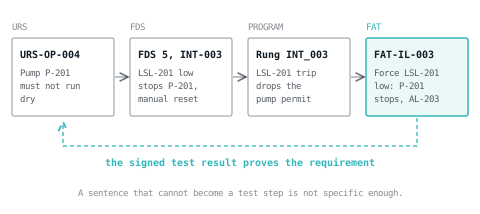
A functional design specification (FDS) is the document that says how a control system will do what the client asked for. It is written before the code, it is approved by the client, and it is the document the factory acceptance test is written from. When a FAT turns into an argument, the argument is almost always about a sentence in the FDS that could be read two ways.
This guide covers the sections a PLC system FDS needs and works through a small pump and tank unit, from one user requirement to a FAT test step. The section numbers match the free FDS template, so you can write as you read.
Where the FDS sits among the other documents
Most confusion about the FDS comes from the documents either side of it. The names vary between companies, so agree them at kick-off.
| Document | Answers | Usually written by | Example sentence |
|---|---|---|---|
| URS, user requirement specification | What the plant must achieve, in plant terms | The client, or the integrator on the client's behalf | The transfer pump shall not run dry. |
| FDS, functional design specification | How the control system meets each requirement | The control systems engineer | LSL-201 low for 2 s stops P-201 and raises AL-203; restart needs a manual reset. |
| Control narrative or control philosophy | Why the process behaves as it does, loop by loop, in operators' language | Process and control engineers | The tank is held between 40 and 70 % so the filter downstream sees a steady head. |
| SDS, software design specification | How the program is built: structure, naming, standard blocks | The lead programmer | Every pump uses FB_Pump; interlocks connect to its Permit input. |
| Cause and effect matrix | Which trip causes which action, as a grid | Process and control engineers together | Row C-07: LSL-201 low stops P-201. |
| FAT protocol | How each FDS statement is proved before the panel ships | The integrator's test engineer | Force LSL-201 low; P-201 stops and AL-203 annunciates. |
On a small machine the URS and FDS are often one document, and the control narrative folds into the FDS sequence section. Keep the requirement numbers even then; they are what make the FAT traceable. The control narrative and software design specification templates exist for projects big enough to need them separately.
A useful test for any sentence in an FDS: could a tester turn it into a test step with a pass condition? 'The pump is protected against dry running' cannot be tested. 'LSL-201 low for 2 s stops P-201' can.
The thirteen sections and what each must contain
These are the sections of the LADX template, in the order a reader needs them. The subsections after the table cover the ones most often written badly.
| # | Section | Must contain | Usual gap |
|---|---|---|---|
| 1 | Purpose and references | Scope, the URS it answers, and the P&ID, I/O list, C&E matrix and risk assessment by number and revision | References with no revision |
| 2 | System architecture | Controllers, remote I/O, drives, HMI, networks and addresses, exact software and firmware versions | 'Latest' instead of a version |
| 3 | Operating modes | Each mode with entry condition, behaviour and exit condition, plus the rules for changing mode | What happens to a running sequence on a mode change |
| 4 | Sequence of operation | Numbered steps, each with an action, a transition, a timeout and a timeout response | Steps with no timeout |
| 5 | Interlocks and permissives | Each one with a reference, condition, device affected, action and reset type | Interlocks and permissives mixed up |
| 6 | Alarms | Tag, description, priority, trip value, delay and the operator action for each alarm | Alarms with no operator action |
| 7 | Analog handling and scaling | Raw and engineering ranges, units, filtering, and the response to an out-of-range signal | Broken-wire behaviour |
| 8 | Operator interface | Screen hierarchy, conventions for device states, security levels | Who may change which setpoint |
| 9 | Data, recipes and reporting | Recipe parameters with ranges and defaults; records with trigger, fields and retention | Retention period |
| 10 | Communications | Every link with its peer, protocol, data exchanged and failure behaviour, including the watchdog | Stale values after a link fails |
| 11 | Failure behaviour | Power loss, CPU fault, I/O comms loss, instrument failure, drive fault: detection, response, recovery | Usually missing entirely |
| 12 | Software structure | Program organisation by POU and language, naming convention, memory map | A naming rule with no examples |
| 13 | Requirement traceability | URS reference, FDS section, where it is implemented, test reference | Left until the end, then skipped |
Operating modes
Write the modes as a table with entry and exit conditions. Then write the mode change rules separately: can the operator switch from Auto to Manual while a sequence is running, and if so, does the sequence pause, abort, or finish its current step? Operators ask that in the first week, and the answer belongs in the FDS rather than in the programmer's head.
Be exact about maintenance modes: list which interlocks are bypassed, who can select the mode, and how it is shown on the HMI.
Sequence of operation
Write each sequence as numbered steps. Every step needs an explicit transition to the next step and a timeout with a stated response, because a step with no timeout can wait forever, and an operator will report it as 'it stopped and nothing happened'. Where a sequence branches or runs in parallel, a Sequential Function Chart drawing is clearer than a table, and the program will usually follow it as a state machine.
Interlocks and permissives
A permissive must be true before something can start. An interlock stops something, or keeps it stopped, when it goes false. Mixing the two produces a machine that cannot be restarted after a trip, or one that restarts by itself when a condition clears. Give each one a reference such as INT-003 or PRM-201 so that the code, the C&E matrix and the FAT all point at the same thing. Where there are more than a handful of trips, put them in a cause and effect matrix and reference it here rather than duplicating it.
Alarms and analog signals
For each alarm, state the priority, the trip value, any delay, and what the operator is expected to do. An indication that needs no operator action is a status message, not an alarm. ISA-18.2 is ISA's standard for the management of alarm systems in the process industries, and alarm rationalisation covers how to decide which alarms deserve to exist.
For each analog input, give the raw range, the engineering range and units, any filtering, and what the program does when the signal leaves its valid range. A broken wire on a flow transmitter can read as zero flow; unless the FDS says how that is detected and what the sequence does about it, the sequence carries on. Analog scaling covers the arithmetic.
A worked example: a transfer pump that must not run dry
Take a small unit: a feed tank T-201 with a low level switch LSL-201, an outlet valve XV-201 with an open limit switch ZSO-201, and a transfer pump P-201 with a run feedback. The URS contains this line:
URS-OP-004: The transfer pump shall not run dry, and shall not restart without operator action after a dry-running stop.
Here is how that one line becomes FDS content. First, section 4, the start sequence:
| Step | Action | Transition to next step | Timeout | On timeout |
|---|---|---|---|---|
| 10 | Wait for start command and permissive PRM-201 | Start command with PRM-201 true | None | None, the step waits |
| 20 | Open XV-201 | ZSO-201 made | 10 s | Raise AL-201 valve failed to open; go to step 900 |
| 30 | Start P-201 | P-201 run feedback made | 5 s | Raise AL-202 pump failed to start; go to step 900 |
| 40 | Running | Stop command (to step 10) or INT-003 (to step 900) | None | None |
| 900 | Faulted: valve closed, pump stopped, alarms held | Reset command with INT-003 clear | None | None |
Then section 5, the interlock and permissive that carry the requirement:
| Ref | Type | Condition | Affects | Action | Reset |
|---|---|---|---|---|---|
| PRM-201 | Permissive | LSL-201 not low and INT-003 not latched | Sequence start | Prevents start | Not applicable |
| INT-003 | Interlock | LSL-201 low for 2 s | P-201 | Stops P-201, raises AL-203, latches | Manual from HMI, accepted only once LSL-201 is healthy |
The FDS now pins down what the URS did not: the signal (LSL-201), the filter (2 s), the response (stop, alarm, latch) and the reset rule. Each is a decision, and making it in the FDS is cheaper than making it on site.
The software design specification says how this is coded. One way, as a step sequence in Structured Text with the interlock acting directly on the output so that a sequence bug cannot bypass it:
(* INT-003: LSL-201 low for 2 s stops P-201 and latches *)
LowTmr(IN := LSL_201_Low, PT := T#2S);
IF LowTmr.Q THEN INT_003 := TRUE; END_IF;
IF ResetCmd AND NOT LSL_201_Low THEN INT_003 := FALSE; END_IF;
AL_203 := INT_003;
PRM_201 := NOT LSL_201_Low AND NOT INT_003;

(* Step timer restarts whenever the step changes *)
StepTmr(IN := (Step = LastStep), PT := StepLimit);
LastStep := Step;

CASE Step OF
  10: (* Wait for start command and permissive *)
    IF StartCmd AND PRM_201 THEN Step := 20; END_IF;
  20: (* Open outlet valve, 10 s to prove open *)
    StepLimit := T#10S;
    IF ZSO_201 THEN Step := 30;
    ELSIF StepTmr.Q THEN AL_201 := TRUE; Step := 900; END_IF;
  30: (* Start pump, 5 s to prove running *)
    StepLimit := T#5S;
    IF P201_RunFb THEN Step := 40;
    ELSIF StepTmr.Q THEN AL_202 := TRUE; Step := 900; END_IF;
  40: (* Running *)
    IF INT_003 THEN Step := 900;
    ELSIF StopCmd THEN Step := 10; END_IF;
  900: (* Faulted, held until reset *)
    IF ResetCmd AND NOT INT_003 THEN
      AL_201 := FALSE;
      AL_202 := FALSE;
      Step := 10;
    END_IF;
END_CASE;

XV201_Open := (Step >= 20) AND (Step <= 40);
P201_Run := (Step = 30 OR Step = 40) AND NOT INT_003;
Each statement in the FDS then becomes at least one FAT step, and each step names the clause it proves:
| Test | Method | Expected result |
|---|---|---|
| FAT-FN-004 | Start with ZSO-201 held unmade | AL-201 after 10 s; XV-201 commanded closed; P-201 never starts |
| FAT-IL-003a | With P-201 running, hold LSL-201 low for 1 s | No trip; P-201 keeps running |
| FAT-IL-003b | With P-201 running, hold LSL-201 low for 3 s | P-201 stops at 2 s; AL-203 annunciates |
| FAT-IL-004 | Restore LSL-201, press start without reset | Nothing starts |
| FAT-IL-005 | Press reset with LSL-201 still low | Trip stays latched |
Section 13 then links URS-OP-004 to INT-003, the rung and these tests, closing the loop drawn at the top of this page: an auditor can pick the requirement and see the signed evidence in a minute.
You do not need the panel to try this: build the interlock and start rungs in the free ladder editor, toggle LSL-201, watch the 2 s timer, and check that start without reset does nothing. A broken reset rule found now costs minutes, not a day on site.
Failure behaviour, the section most FDS documents leave out
Section 11 describes the plant failing, and it is the section most often left as an empty heading. For each item below, state how the failure is detected, what the system does, which alarm is raised, and how the operator recovers.
- Power loss and return. Do outputs come back on by themselves when power returns? Usually they must not. Say which step every sequence starts in; the logic lives in the first scan.
- Controller stop, or remote I/O loss. What the outputs do, how long before a lost node counts as a fault, and whether hardwired protection covers the gap.
- Loss of a link to SCADA or another PLC. The watchdog timeout, and what happens to a value that has stopped updating. A link with no watchdog will one day deliver a stale value that looks valid.
- Instrument failure. Which signal levels count as failed, and whether the program holds the last value, substitutes a safe value or trips.
- Drive fault. Whether the sequence stops, holds, or swaps to a standby unit.
- Emergency stop and recovery. Which stop category the E-stop uses, what stays energised, and what must happen before motion is possible again. Stop categories explains the choices.
Writing statements that can be tested
| Vague | Testable |
|---|---|
| The pump is protected against dry running. | LSL-201 low for 2 s stops P-201 and raises AL-203. |
| The valve opens quickly. | XV-201 must prove open within 10 s of the open command, or AL-201 is raised. |
| Alarms are displayed appropriately. | AL-203 is High priority, appears in the alarm banner and needs acknowledgement. |
| The system recovers safely after a power failure. | After power returns, every sequence starts in step 10 and no output energises until a start command. |
Before issuing a revision, search for 'appropriately', 'as required', 'quickly', 'normally' and 'TBC'. Each marks a decision not yet made.
What goes wrong in practice
- The FDS is written after the code. It then describes what the program does, and a FAT written from it tests that the program does what it does. GAMP 5 is blunt about this: specify first.
- It contradicts another document. The FDS says 2 s and the C&E matrix says 5 s. Say which document wins. The City of Winnipeg's published functional requirements specification for a clarifier PLC, for example, states that the process control narratives, P&IDs and loop drawings take precedence over it if they disagree.
- The program and the FDS revisions drift apart. An FDS approved at revision B while the program implements revision D is a common FAT finding. Put the FDS revision in the program header and change both together.
- Traceability is left to the end. By then nobody remembers which requirement a clause answers. Fill in section 13 as you write each section.
Standards and references to cite
No single international standard is titled 'functional design specification', so cite what your industry uses.
- ISA-5.06.01-2007, Functional Requirements Documentation for Control Software Applications, which ISA describes as establishing functional requirements specifications for control software documentation.
- ISPE GAMP 5, second edition (published July 2022) is ISPE's guide to a risk-based approach for GxP computerised systems, which ISPE describes as the leading international guidance on their validation and compliance. It notes that its specification and verification approach is not inherently linear and also supports iterative and incremental methods.
- The LADX template's reference list adds IEC 61131-3, ISA-88, ISA-18.2 and IEC 60204-1.
For how much documentation a project needs, see documentation people actually read; for drafting the prose with a model once the decisions are made, see AI for PLC documentation.
Starting from the template
The LADX FDS template has the thirteen sections above with their tables in place, from hardware and software versions through the mode, sequence, interlock, alarm and failure tables to the traceability table. It downloads free as a Markdown file, with no account, and you can enter the project name, client, company and author before downloading so it arrives filled in.
It sits with the URS template, the cause and effect matrix and the FAT protocol, which is written from the FDS. Write the FDS, write the FAT from it, and fill in the traceability table as you go.
Sources and further reading
- ISA-5.06.01-2007, Functional Requirements Documentation for Control Software Applications (ISA)isa.org
- Good automated manufacturing practice, GAMP (Wikipedia)en.wikipedia.org
- City of Winnipeg Bid Opportunity 682-2018, Appendix F: a published PLC functional requirements specification (PDF)legacy.winnipeg.ca
- ISA-18 series of alarm management standards (ISA)isa.org
Common questions
- What is the difference between an FDS and a URS?
- The URS is the client's statement of what the plant must achieve, written in plant terms and without saying how. The FDS is the engineer's answer: how the control system meets each numbered requirement, with signals, timings, modes and failure responses. Every FDS clause should trace back to a URS number, and every URS line forward to a test.
- Is a control philosophy the same as a functional design specification?
- Not quite, although companies use the names loosely. A control philosophy or control narrative explains in prose why the process is controlled the way it is, loop by loop. An FDS turns that into testable detail: numbered steps, transitions, timeouts, interlock references and alarm settings. On a small machine one document can do both jobs if it keeps the detail.
- Who approves a functional design specification?
- The control systems engineer writes it and the client approves it, normally the client's engineering lead together with the process owner, with quality added on regulated projects. Approval matters because the FDS becomes the basis of the FAT: once it is signed, a disagreement about behaviour is settled by what the document says, not by anyone's memory.
- How long should an FDS for a PLC system be?
- As long as it takes to make every behaviour testable, and no longer. A small machine may need fifteen pages; a process unit with several sequences and a long alarm list may need a hundred. Tables keep it short: a sequence written as a step table takes a fraction of the space of the same sequence written as prose.
- Can the FDS be changed after the FAT?
- Yes, through change control. Changes found at FAT or during commissioning should be raised, approved and written into a new FDS revision, and the affected tests repeated. An FDS that stops being updated after the FAT soon describes a different system from the one running, which is exactly when somebody will need it to be right.
Keep reading
- Compliance
Factory acceptance test checklist for a PLC control panel
A FAT checklist you can copy for a PLC panel: documents, inspection, power-up, I/O point by point, interlocks, alarms, HMI, safety, failure modes, sign-off.
- Compliance
GAMP 5 for control engineers, without the consultancy
Software categories, the V model, risk based effort, and what actually changes about how you write and test a PLC program.
- AI
The one AI task in automation with no downside
Documentation is the most disliked, most billable and least risky thing to hand to a machine.