

Factory acceptance test checklist for a PLC control panel
A FAT checklist you can copy for a PLC panel: documents, inspection, power-up, I/O point by point, interlocks, alarms, HMI, safety, failure modes, sign-off.
By the LADX engineering team
Short answer
A PLC panel FAT checklist covers, in order: entry criteria and documents, visual and mechanical inspection, power-up and electrical tests, every I/O point, functional tests from the FDS, every interlock and safety function, alarms and HMI, communications and failure modes, a graded punch list, and signatures. Each check records the expected and actual result, the tester and the date.
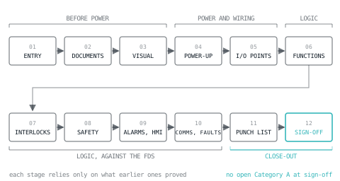
A factory acceptance test proves that the panel does what the functional design specification says, while it is still on the bench, the programmer is in the building and a spare part is a drawer away. The checklist below is written to be copied into a protocol and carried out, section by section, on the witness day and on the internal dry run before it.
The order follows one rule: each stage relies only on what earlier stages have proved. Documents before power, power before I/O, I/O before logic. The difference between FAT and SAT, and where commissioning starts, is covered in the commissioning checklist; this article stays on the FAT itself.
For process automation, IEC 62381:2024, edition 3, is the reference. It covers the FAT, the site acceptance test and the site integration test, adds an optional factory integration test, and replaces the old annex forms with activity checklists for writing project-specific plans.
Before the FAT: entry criteria
The FAT does not start until every line here is true. A FAT started early produces a punch list that is really a build list.
| # | Criterion | Evidence |
|---|---|---|
| E1 | Panel build complete and internally inspected | Signed build sheet |
| E2 | PLC program compiled, version and checksum recorded | Version record |
| E3 | HMI application complete, version recorded | Version record |
| E4 | Internal pre-FAT run against this protocol, faults cleared | Pre-FAT record |
| E5 | Simulation rig built and proven | Rig check |
| E6 | FDS, I/O list, cause and effect matrix, schematics and BOM at current revision | Document register |
| E7 | Protocol issued to the client in advance (the LADX template says five working days) | Transmittal |
| E8 | Test equipment calibration in date | Certificates |
1. Documentation
| # | Check | Result |
|---|---|---|
| D1 | Schematics match the panel as built, sheet by sheet | Pass / Fail |
| D2 | BOM matches installed components, item by item | Pass / Fail |
| D3 | I/O list matches the program's tags and addresses | Pass / Fail |
| D4 | Manuals and datasheets present for every bought-in device | Pass / Fail |
| D5 | Declarations prepared for the destination market | Pass / Fail |
| D6 | Spare parts list supplied | Pass / Fail |
2. Visual and mechanical inspection
| # | Check | Result |
|---|---|---|
| V1 | Enclosure undamaged, correct IP rating, seals intact | |
| V2 | Components mounted securely, clearances as per manufacturers | |
| V3 | Wiring ferruled, numbered and identified as the drawings | |
| V4 | Wire colours match the legend sheet | |
| V5 | Power, control, analogue and network segregated | |
| V6 | Every metal part bonded, door and plate straps fitted | |
| V7 | Labels and warning signs fitted, including excepted circuits | |
| V8 | Isolator door interlock works | |
| V9 | Gland plate correct, spare entries blanked, no swarf |
Check V4 against the colour scheme on the drawings, not memory; the wire colour codes article sets out what NFPA 79 and IEC 60204-1 expect.
3. Power-up and electrical tests
Dead tests first, then power in stages. For machine electrical equipment, clause 18 of IEC 60204-1 defines the verification. In the 2016 edition with its 2021 amendment, 18.2 covers protection by automatic disconnection of supply (Test 1, continuity of the protective bonding circuit, and Test 2, fault loop impedance), 18.3 insulation resistance, 18.4 voltage tests, 18.5 protection against residual voltages, 18.6 functional tests and 18.7 retesting after modification.
| # | Test | Method | Record |
|---|---|---|---|
| P1 | Protective bonding continuity | Low-voltage test current between the PE terminal and each bonding point | Resistance per point |
| P2 | Insulation resistance | Insulation tester between power circuits and the protective bonding circuit, with surge protective devices handled as the standard allows | Test voltage and reading |
| P3 | Protective devices | Ratings and settings against the schematic | Pass / Fail |
| P4 | Incoming supply | Voltage and phase rotation at the isolator | Measured values |
| P5 | Control supplies | 24 V DC under load, and ripple, at the furthest consumer | Measured values |
| P6 | Staged energising | One circuit at a time, PLC last | Pass / Fail |
For reference, the 2005 edition of IEC 60204-1 (as published in JIS B 9960-1:2008) specified a continuity test current between 0.2 A and about 10 A from a source of no more than 24 V, and at least 1 MΩ insulation resistance at 500 V DC between power circuits and the protective bonding circuit. Take the values from the edition your contract names, and record them.
4. I/O check, point by point
Every point on the I/O list, individually. It is the slowest section and the one that saves the most later, because a crossed pair found here costs five minutes. The method, as RealPars describes it, is to simulate at the terminals: a jumper or switch for passive inputs, a signal simulator for active devices, and a calibrator in current mode for 4-20 mA.
| Tag | Address | Terminal | Simulated | Expected in PLC | Observed | Result | Initials, date |
|---|---|---|---|---|---|---|---|
| XV-101-ZSO | %I0.0 | X2:3 | Switch closed | TRUE, no other bit changes | |||
| MTR-101-RUN | %Q0.0 | X5:1 | Forced on | 24 V at X5:1, lamp lit, no other output | |||
| FT-101 | %IW64 | X3:1 | 4 / 12 / 20 mA | 0.0 / 25.0 / 50.0 m3/h | |||
| FT-101 | %IW64 | X3:1 | Wire removed | Wire-break alarm, defined fail value | |||
| FCV-101 | %QW96 | X6:1 | 0 / 50 / 100 % | 4 / 12 / 20 mA on calibrator |
Work the expected analog values out before the day, from the I/O list's range, so nobody does arithmetic in front of the witness. The calculation is the 4-20 mA scaling line:
FUNCTION ExpectedEU : REAL
VAR_INPUT
    mA    : REAL;  (* injected by the calibrator *)
    EU_Lo : REAL;  (* engineering value at 4 mA, from the I/O list *)
    EU_Hi : REAL;  (* engineering value at 20 mA *)
END_VAR
ExpectedEU := EU_Lo + (mA - 4.0) * (EU_Hi - EU_Lo) / 16.0;
END_FUNCTION
For FT-101, ranged 0 to 50 m3/h, 12 mA gives 0 + 8 × 50 / 16 = 25.0 m3/h. Record the observed value, not just a tick; a reading of 24.6 against 25.0 is a calibration question, and a tick hides it.
5. Functional tests from the FDS
Every test quotes the FDS clause it proves, so a passed FAT means the FDS is met, and a gap between them is found here.
| Ref | FDS | Test | Expected |
|---|---|---|---|
| FN-01 | 3 | Select each mode at the HMI | Mode changes and is indicated |
| FN-02 | 4.1 | Satisfy permissives, press Start | Steps run in FDS order |
| FN-03 | 4.1 | Withhold the step 2 transition | Timeout alarm, sequence holds |
| FN-04 | 4.3 | Press Stop mid-cycle | Cycle completes, then stops |
| FN-05 | 4.5 | Remove and restore control power | No automatic restart; reset needed |
| FN-06 | 4.5 | Power-cycle with recipe and counters set | Retentive values survive, as specified |
6. Interlocks, from the cause and effect matrix
The cause and effect matrix is the most testable document on the project: each mark is one FAT test. Test the marks and confirm the blanks, because an effect that happens when it should not is as much a failure as one that does not happen.
Three rows of a matrix:
| Cause | P-101 stop | XV-101 close | FCV-101 to fail position | Horn |
|---|---|---|---|---|
| C-001 E-stop pressed | X | X | X | X |
| C-002 Guard door open | X | X | ||
| C-003 LT-101 above 95 % | X | X | X |
become these steps:
| Step | Simulate | Confirm happens | Confirm does not happen |
|---|---|---|---|
| IL-01 | Press E-stop | P-101 stops, XV-101 closes, FCV-101 to fail position, horn | Nothing restarts on release |
| IL-02 | Open guard door | P-101 stops, horn | XV-101 stays open, FCV-101 stays in control |
| IL-03 | Inject LT-101 at 95.5 % | P-101 stops, XV-101 closes, horn | FCV-101 stays in control |
IL-02 is the one that catches mistakes: a guard switch wired into the same chain as the E-stop passes every mark in its row and fails the blanks.
7. Safety functions
| # | Test | Expected |
|---|---|---|
| S1 | Each safety input, channel A open alone | Function trips, fault annunciated |
| S2 | Each safety input, channel B open alone | Function trips, fault annunciated |
| S3 | Channels opened beyond the discrepancy time | Fault detected and latched |
| S4 | Reset with the E-stop still pressed | Reset refused |
| S5 | Reset button held closed when the guard closes | No restart; reset needs a new press |
| S6 | Stop category as specified | As per the stop category in the FDS |
| S7 | Response time | Within the calculated figure |
S5 catches the commonest reset fault: a reset that acts on a level rather than an edge re-enables the machine the moment the guard closes if the button has stuck. Whether the logic sits in a relay or a safety PLC, the test is the same. Validation of the safety functions on the machine itself follows on site.
8. Alarms
| # | Test | Expected |
|---|---|---|
| A1 | Raise each alarm from its real cause | Correct text, priority and time stamp |
| A2 | Acknowledge | User and time recorded |
| A3 | Clear the cause | Alarm returns to normal as designed |
| A4 | Several alarms at once | Shown in time order |
| A5 | Power-cycle the HMI | Alarm history retained |
Trigger alarms from the cause, not by forcing the alarm bit; forcing proves the screen, not the logic. Alarm design covers what a good alarm list looks like before you test it.
9. HMI
| # | Test | Expected |
|---|---|---|
| H1 | Every screen reached from the navigation | No dead ends |
| H2 | Every button and set-point | Writes the right tag, within limits |
| H3 | Every displayed value | Matches the PLC, with units |
| H4 | Each user level | Only permitted actions available |
| H5 | HMI disconnected | Control continues, communication alarm raised |
10. Communications and failure modes
| # | Inject | Expected |
|---|---|---|
| F1 | Remote I/O cable pulled | Communication alarm, outputs to their defined state |
| F2 | Link to another system lost | Timeout detected, defined action, no stale data on recovery |
| F3 | Analog input open circuit | Fault detected, alarm, defined fail action |
| F4 | 24 V DC removed | Outputs de-energise, orderly behaviour on return |
| F5 | CPU to stop | Outputs de-energise |
These are the tests most checklists leave out, and the faults most likely to happen in the first year.
11. Punch list and sign-off
Every fault goes on the punch list with an owner and a date. The LADX template grades them in two: Category A stops the system doing a specified function or is a safety issue, and must be closed before despatch; Category B is cosmetic, documentation, or does not prevent use, and may be closed on site by agreement. Nothing ships with an open Category A.
At sign-off, record the program version and checksum that was tested, beside the signatures of the test engineer, quality, the client's witness and the project manager. Any change after that goes through version control and a retest of what it touched.
Dry-run the logic before the witness day
Most FAT time is lost to logic faults found while the witness watches. Run the sequences and interlocks through the LADX ladder editor first: it simulates the scan with an output image, edge memory per instruction and millisecond timers, so permissive and timeout behaviour show up at a desk. Bind the alarm list to those tags in the HMI builder to see the ISA-18.2 alarm states before the HMI is built. It is a simulator: it finds logic faults, not wiring faults.
The template and a signed record
The free FAT protocol template contains every section above, in 14 parts from scope to acceptance, written against IEC 62381, with the I/O, interlock, safety and failure tables ready to fill. It downloads as Markdown without an account, alongside the SAT protocol that follows it on site.
To carry the test out as a record rather than a printout, LADX Studio, a free account, can start a FAT run against a project. Each step gets a pass, a fail or a note, on a phone if that is where you are, and the run is signed off with a name and role. Signing closes the run and goes into the audit log; reopening removes the signature and is logged too. The signed run is then written up as a project document that can be shared and exported.
What goes wrong at a FAT
- Starting before the entry criteria are met. The witness watches you finish the build.
- A partial I/O check. Twenty points checked out of two hundred is not an I/O check.
- Marks tested, blanks not. The interlock that does too much passes.
- Untracked program changes. A fix made at 3 pm and not recorded means the signed version is not the one that ships.
- Simulation mistaken for proof. A FAT proves the panel and the logic. Field devices, cable runs and real process timing belong to the SAT.
- Signatures without witnessing. A witness who signs pages they did not see has accepted nothing.
Sources and further reading
- IEC 62381:2024, FAT, SAT and SIT for automation systems in the process industry (IEC)webstore.iec.ch
- IEC 60204-1:2016, electrical equipment of machines, including clause 18 Verification (IEC)webstore.iec.ch
- Factory acceptance test explained: simulating panel I/O (RealPars)realpars.com
- Acceptance testing (Wikipedia)en.wikipedia.org
Common questions
- How long does a FAT on a PLC panel take?
- It depends on the point count and the number of sequences far more than on the panel size. Estimate from the protocol: count the I/O points, the functional tests, the cause and effect marks and the failure tests, time a few of each in the pre-FAT, and multiply. The witnessed run should be quicker than the internal one.
- Who signs a factory acceptance test?
- Typically the builder's test engineer and quality representative, and the client's witness and project manager, as the LADX template's signature block sets out. The client signs to accept the result, not to take responsibility for the design. Each signature should sit beside the program version and checksum that was tested.
- Is there a standard for factory acceptance tests?
- IEC 62381:2024, edition 3, covers FAT, SAT and site integration testing for automation systems in the process industries, and adds an optional factory integration test. Its annexes are activity checklists for writing project-specific test plans. For machine electrical equipment, clause 18 of IEC 60204-1 sets out the verification tests.
- Can a FAT be done with simulated I/O?
- Yes, and usually it is: switches or jumpers for digital inputs, lamps or a meter on outputs, and a loop calibrator for 4-20 mA signals. Simulation proves the panel and the logic. It cannot prove field devices, cable runs or process behaviour, which is why every loop is checked again at the SAT.
- What is a Category A punch list item?
- In the LADX FAT template, Category A is anything that stops the system performing a specified function, or any safety issue, and it must be closed before the panel ships. Category B covers cosmetic and documentation items, or faults that do not prevent use, and may be closed on site by agreement.
Keep reading
- Compliance
Functional design specification for a PLC system: what goes in it
What a functional design specification for a PLC control system contains, section by section, with a worked sequence table and one requirement traced to FAT.
- Panel & Electrical
Control panel wire colour codes: NFPA 79 vs IEC 60204-1
Which colour each conductor gets under NFPA 79 (2024) and IEC 60204-1, clause by clause, what is mandatory, and a legend for a panel built for both.
- Safety
Cause and effect matrix: how to write one for control and safety
How to lay out, read and test a cause and effect matrix for interlocks and trips, including voting, latching, reset and bypass, with a worked example.