

Logic gates in ladder logic: AND, OR, NOT, NAND, NOR, XOR, XNOR
Every logic gate as a ladder rung with its truth table, why NAND and NOR are drawn the way they are, and how XOR on bits differs from XOR on words.
By the LADX engineering team
Short answer
In ladder logic, contacts in series make AND, contacts in parallel make OR, and an examine-off (XIO) contact makes NOT. The other gates are combinations: NAND is two XIO contacts in parallel, NOR is two XIO contacts in series, XOR is two parallel legs each with one XIC and one XIO, and XNOR is one leg of two XIC contacts beside one leg of two XIO contacts.
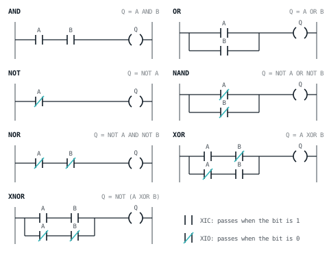
A rung is a Boolean expression drawn as a circuit. Power reaches the coil if there is a path of passing contacts from the left rail, so the shape of the rung is the logic. Switching circuit theory, published independently by Akira Nakashima, Claude Shannon and Victor Shestakov in the mid-1930s, showed that Boolean algebra describes circuits of switches, and ladder logic is that idea in software.
Two instructions do all the work. XIC (examine if closed) passes power when its bit is 1. XIO (examine if open) passes power when its bit is 0. They examine a bit in memory, not a physical switch, which is why a normally closed stop button is examined with XIC. Keep that distinction in mind: an XIO in a rung and a normally closed contact in the field are different things.
| Gate | Expression | Rung | ST equivalent |
|---|---|---|---|
| AND | A AND B | XIC(A)XIC(B)OTE(Q) | Q := A AND B; |
| OR | A OR B | [XIC(A),XIC(B)]OTE(Q) | Q := A OR B; |
| NOT | NOT A | XIO(A)OTE(Q) | Q := NOT A; |
| NAND | NOT (A AND B) | [XIO(A),XIO(B)]OTE(Q) | Q := NOT (A AND B); |
| NOR | NOT (A OR B) | XIO(A)XIO(B)OTE(Q) | Q := NOT (A OR B); |
| XOR | A XOR B | [XIC(A)XIO(B),XIO(A)XIC(B)]OTE(Q) | Q := A XOR B; |
| XNOR | NOT (A XOR B) | [XIC(A)XIC(B),XIO(A)XIO(B)]OTE(Q) | Q := NOT (A XOR B); |
Each gate below has its rung and its truth table. Every rung runs in the free ladder simulator: declare A, B and Q as BOOL tags, make A and B selector switches, and step through the four rows.
AND: contacts in series
XIC(A)XIC(B)OTE(Q);| A | B | Q |
|---|---|---|
| 0 | 0 | 0 |
| 0 | 1 | 0 |
| 1 | 0 | 0 |
| 1 | 1 | 1 |
Power has to pass both contacts. Every permissive in a program is an AND: a motor runs when it is started, and the guard is closed, and the overload is healthy.
OR: contacts in parallel
[XIC(A),XIC(B)]OTE(Q);| A | B | Q |
|---|---|---|
| 0 | 0 | 0 |
| 0 | 1 | 1 |
| 1 | 0 | 1 |
| 1 | 1 | 1 |
Either leg is enough. A common alarm lamp that lights for any of several faults is an OR, and so is the seal-in branch that holds a motor on.
NOT: one XIO contact
XIO(A)OTE(Q);| A | Q |
|---|---|
| 0 | 1 |
| 1 | 0 |
The output is the inverse of the input. A Ready lamp that lights when there is no fault is XIO(Fault)OTE(Ready). A NOT inverts; a buffer, which some lab sheets confuse with it, passes the input through unchanged.
NAND: two XIO contacts in parallel
[XIO(A),XIO(B)]OTE(Q);| A | B | Q |
|---|---|---|
| 0 | 0 | 1 |
| 0 | 1 | 1 |
| 1 | 0 | 1 |
| 1 | 1 | 0 |
The output is off only when both inputs are on. A Door_Open lamp fed by two door-closed switches is a NAND: it lights unless both doors are closed. The usual mistake is to draw the two XIO contacts in series, which is a NOR and gives a lamp that lights only when both doors are open.
NOR: two XIO contacts in series
XIO(A)XIO(B)OTE(Q);| A | B | Q |
|---|---|---|
| 0 | 0 | 1 |
| 0 | 1 | 0 |
| 1 | 0 | 0 |
| 1 | 1 | 0 |
The output is on only when both inputs are off. XIO(Fault_A)XIO(Fault_B)OTE(Ready) is a NOR, and it reads naturally: ready when there is no fault A and no fault B.
XOR: two legs, one of each
[XIC(A)XIO(B),XIO(A)XIC(B)]OTE(Q);| A | B | Q |
|---|---|---|
| 0 | 0 | 0 |
| 0 | 1 | 1 |
| 1 | 0 | 1 |
| 1 | 1 | 0 |
On when the inputs differ. The top leg passes for A without B, the bottom leg for B without A, and neither passes when they agree. A two-way stair light switched from either end is an XOR.
XNOR: both on, or both off
[XIC(A)XIC(B),XIO(A)XIO(B)]OTE(Q);| A | B | Q |
|---|---|---|
| 0 | 0 | 1 |
| 0 | 1 | 0 |
| 1 | 0 | 0 |
| 1 | 1 | 1 |
On when the inputs agree, which makes XNOR an equality check for two bits.
Why NAND is parallel and NOR is series
De Morgan's laws are two rules for moving a NOT through an expression:
- NOT (A AND B) is the same as (NOT A) OR (NOT B).
- NOT (A OR B) is the same as (NOT A) AND (NOT B).
In ladder they become one drawing rule: to invert a whole rung, invert every contact and swap series for parallel. NAND is NOT (A AND B), so it becomes two XIO contacts in parallel; NOR becomes two XIO contacts in series. That is why the gate drawings look the opposite of what their names suggest.
There are two other ways to get the inversion. Compute A AND B into an intermediate bit on one rung and examine it with XIO on the next. Or, on Siemens, use the LAD NOT contact, which inverts the power flow arriving at it, so a NAND can be drawn as two contacts in series followed by NOT.
The same gates in Structured Text
Q_and  := A AND B;
Q_or   := A OR B;
Q_not  := NOT A;
Q_nand := NOT (A AND B);
Q_nor  := NOT (A OR B);
Q_xor  := A XOR B;
Q_xnor := NOT (A XOR B);  (* for BOOL, the same as A = B *)
In Structured Text the gates are operators, which is why long Boolean conditions are often easier to read in ST than as a tall rung. To see your own rungs translated, export the project from the ladder editor and open it in Convert, which writes IEC 61131-3 Structured Text, Siemens SCL, neutral text or PLCopen XML and reports anything it could not translate. The IEC 61131-3 languages article covers where each language fits.
XOR with three inputs is odd parity
Chaining XOR does not mean "exactly one input is on". CODESYS documents that its XOR with more than two inputs compares the inputs in pairs and then compares the results, in line with the standard, and notes this may not match expectations. Worked through, the result is true when an odd number of inputs are on: one, or all three.
[XIC(A)XIO(B),XIO(A)XIC(B)]OTE(AB_Xor);
[XIC(AB_Xor)XIO(C),XIO(AB_Xor)XIC(C)]OTE(Q_Odd);
[XIC(A)XIO(B)XIO(C),XIO(A)XIC(B)XIO(C),XIO(A)XIO(B)XIC(C)]OTE(Q_One);
The first two rungs are a chained XOR, and Q_Odd is on for one input or for three. The third rung is what "exactly one of three" really looks like: one leg per input, each with the other two examined off. With all three inputs on, Q_Odd is on and Q_One is off.
XOR on words is a different instruction
Everything above works on single bits. Rockwell's ladder XOR instruction is bitwise: it takes Source A and Source B, integers, and writes Source A XOR Source B into Dest, bit by bit. It is not a contact, and in Logix Structured Text the same job is done with XOR as an operator in an expression. CODESYS accepts XOR on BOOL, BYTE, WORD, DWORD and LWORD, and its help gives 2#1001_0011 XOR 2#1000_1010, which is 2#0001_1001: a 1 wherever the two words differ.
That makes word XOR the quick way to find which bits changed between scans: XOR this scan's input word with last scan's copy and every 1 in the result is a bit that moved. The LADX simulator has no XOR instruction, so this one is for a real controller or a CODESYS soft PLC.
Where the gates turn up in real programs
Discrepancy checks. Two channels that should agree, such as two contacts on the same guard switch, are compared with XOR. A short difference is normal while the contacts move, so the XOR feeds a timer and only a lasting disagreement latches a fault.
[XIC(Ch_A)XIO(Ch_B),XIO(Ch_A)XIC(Ch_B)]TON(Disc_Tmr,500,0);
XIC(Disc_Tmr.DN)OTL(Disc_Fault);
XIC(Reset_PB)XIO(Disc_Tmr.EN)OTU(Disc_Fault);
The reset only works while the channels agree, because the timer's enable bit follows the XOR. If the two channels are wired as one normally open and one normally closed contact, healthy means always different, and the check becomes XNOR. A check like this in a standard PLC is diagnostics. A guard that protects people needs a safety-rated function, which is the subject of safety relays and safety PLCs.
Toggles. A light switched from two places is XOR. A pushbutton toggle is XOR of the light and a one-scan pulse, which is Problem 2 in the ladder logic practice problems.
Permissives and summaries. Permissives are ANDs, summaries are ORs, and anything phrased "unless both" is a NAND. When a rung is hard to read, write its expression down, apply De Morgan, and see whether the other form is shorter.
Simplifying a rung with the same algebra
Rungs grow branches as a machine is modified, and Boolean algebra is how you prune them without changing what they do. A worked example:
[XIC(Auto)XIC(Ready),XIC(Auto)XIO(Ready),XIC(Manual)XIC(Jog)]OTE(Run);
[XIC(Auto),XIC(Manual)XIC(Jog)]OTE(Run);
The first rung is (Auto AND Ready) OR (Auto AND NOT Ready) OR (Manual AND Jog). The first two legs together are Auto AND (Ready OR NOT Ready), and Ready OR NOT Ready is always true, so they reduce to Auto, and the second rung is the same logic. Ready turns out never to have mattered, which is worth asking about before deleting it: someone may have meant it to. Check any simplification the same way as the gates above, by listing every input combination and comparing the two outputs row by row.
Mistakes that look right
- NAND drawn in series. Two XIO contacts in series are a NOR. The lamp works for the both-open case you tested and fails for the one-open case you did not.
- Inverting twice. A normally closed field device already reads 1 when healthy. Examining it with XIO as well, because the device is normally closed, inverts it a second time.
- Latching a gate. Gates are combinational: the output follows the inputs on every scan. An OTL turns a gate into memory that no longer follows them, so use OTE.
- Chained gates in the wrong order. In the three-input XOR above, the rung that writes
AB_Xormust sit above the rung that reads it. Swap them andQ_Oddis calculated from the previous scan'sAB_Xor, which is wrong for one scan after every change, enough to trigger a one-shot or a counter downstream.
Sources and further reading
- Logic gate (Wikipedia)en.wikipedia.org
- De Morgan's laws (Wikipedia)en.wikipedia.org
- CODESYS online help: Operator XORcontent.helpme-codesys.com
- Rockwell Logix 5000 Controllers General Instructions reference (1756-RM018), Bitwise Exclusive Or (XOR), p. 501literature.rockwellautomation.com
- Siemens S7-1200 Programmable Controller system manual (LAD NOT contact)cache.industry.siemens.com
Common questions
- Is there an XOR instruction for bits in Studio 5000?
- Not as a contact. The ladder XOR instruction in Logix is bitwise: it takes Source A and Source B and writes the result to a destination word. For single bits, build XOR from two parallel legs of XIC and XIO contacts. In Logix Structured Text, XOR is used as an operator in an expression.
- What is a universal logic gate?
- A gate that can build every other gate on its own. NAND and NOR are both universal: any Boolean function can be made from NAND gates alone, or from NOR gates alone. In ladder this matters little, because XIC and XIO contacts in series and parallel already express any function directly.
- Is XNOR the same as checking two bits are equal?
- Yes. XNOR is true when both inputs are 0 or both are 1, which is equality. In Structured Text, A = B on two BOOL values gives the same result as NOT (A XOR B). For integers use an EQU comparison instead, which compares whole values rather than single bits.
- Does Siemens LAD have a NOT instruction?
- Yes. Siemens LAD has a NOT contact that inverts the power flow arriving at it, so NAND can be drawn as two contacts in series followed by NOT. Rockwell-style ladder is normally written with XIO contacts instead, using De Morgan's laws to move the inversion onto each input.
- Why do PLC programmers still learn logic gates?
- Because every rung is a Boolean expression, and reading one quickly means seeing the gate in it. Interlocks are ANDs, alarm summaries are ORs, discrepancy checks are XORs, and a NAND drawn wrong is a real fault that passes a quick look. Function Block Diagram also shows the gates as boxes.
Keep reading
- Languages
Ladder logic to Structured Text: converters, rules and pitfalls
How a rung becomes Structured Text, the rules a converter must follow for timers, edges and latches, and the rungs that convert wrongly unless you test them.
- Fundamentals
The output image: why your coil did not work
A coil sets a bit in memory, not a terminal. Understanding when that memory reaches the real world explains a whole class of bugs.
- Practice
PLC ladder logic practice problems with solutions you can run
Nine graded ladder logic exercises, each with a spec, a worked solution, a scan-by-scan explanation and the wrong answer most people write first.