

Ladder logic to Structured Text: converters, rules and pitfalls
How a rung becomes Structured Text, the rules a converter must follow for timers, edges and latches, and the rungs that convert wrongly unless you test them.
By the LADX engineering team
Short answer
Most rungs convert mechanically: series contacts become AND, a parallel branch becomes OR in brackets, an OTE becomes an assignment that runs every scan, and OTL or OTU become an IF with no ELSE. Timers, counters and one-shots become function block instances that must also be called every scan. A converter handles the simple rungs; test timers, edges and rung order yourself.
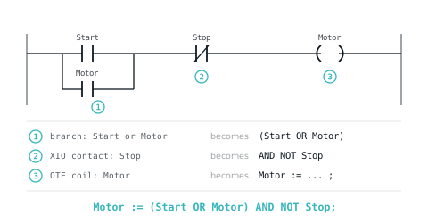
Search for a ladder logic to Structured Text converter and most of what comes back is forum threads, many of them a decade old, ending in some version of 'do it by hand'. The truth is in between. Most rungs translate mechanically and a tool can do that part. A handful of rung shapes translate into code that compiles, looks right and behaves differently, and those are what this article is about.
It assumes you can read ST already. If not, Structured Text for people who think in ladder covers the basic mapping in a few minutes; this piece covers the rules a conversion has to obey and how to prove that it did.
Why the IDE will not do it for you
Ladder Diagram, Function Block Diagram and Instruction List are network languages. A routine is a list of networks, and each network is a boolean structure driving coils or boxes. That shared model is what lets an editor switch between them: the CODESYS help notes that an IL program must contain at least one network so that it can be converted to FBD or LD.
Structured Text has no networks. It is a sequence of statements, and a statement can do things a rung cannot, such as skip a function block call entirely. Moving a ladder routine to ST is therefore a rewrite, whoever or whatever does the writing, and the result has to be checked the way a rewrite would be. The five languages and where each fits are compared in IEC 61131-3 languages.
The mapping, instruction by instruction
The ladder column is Rockwell neutral text, the form rungs take inside an L5X export. The IEC column is what CODESYS and other IEC 61131-3 tools accept. The Logix column is Rockwell's own published ST form, from the import/export and instruction reference manuals.
| Ladder | IEC 61131-3 ST | Logix ST | Watch for |
|---|---|---|---|
XIC(A)XIO(B)OTE(C); | C := A AND NOT B; | C [:=] A AND NOT B; | Runs every scan, outside any IF |
[XIC(A),XIC(B)]XIC(D)OTE(C); | C := (A OR B) AND D; | C [:=] (A OR B) AND D; | Brackets: AND binds tighter than OR |
XIC(A)OTL(C); | IF A THEN C := TRUE; END_IF; | IF A THEN C := 1; END_IF; | No ELSE, so the bit holds |
XIC(A)OTU(C); | IF A THEN C := FALSE; END_IF; | IF A THEN C := 0; END_IF; | Keep the latch and unlatch in their original order |
XIC(A)ONS(A_os)OTE(P); | A_trig(CLK := A); P := A_trig.Q; | A_os.InputBit := A; OSRI(A_os); P := A_os.OutputBit; | One instance per edge |
XIC(A)TON(T1,5000,0); | T1(IN := A, PT := T#5S); | T1.TimerEnable := A; T1.PRE := 5000; TONR(T1); | Called every scan; .DN becomes .Q in IEC |
XIC(A)RES(T1); | No reset input on IEC TON: drive IN false | T1.Reset := A; on the TONR | RES has no direct IEC twin |
XIC(A)RTO(T2,5000,0); | A TON is not retentive: the hold needs logic of its own | RTOR(T2); | A plain TON loses the accumulated time |
GRT(Level,80)OTE(High); | High := Level > 80; | High [:=] Level > 80; | Compare instructions are just expressions |
XIC(A)MOV(5,X); | IF A THEN X := 5; END_IF; | IF A THEN X := 5; END_IF; | Keeps the old value when A is false |
Rockwell's ST timer, TONR, takes an FBD_TIMER tag with TimerEnable, PRE and Reset inputs and a DN output; RTOR is its retentive sibling (1756-RM003). The CODESYS TON takes IN and PT and returns Q and ET, and resets on a falling edge of IN.
A worked example
Seven rungs from a small conveyor: a seal-in, a delayed fan start, a part count and an alarm latch. In neutral text:
[XIC(Start_PB),XIC(Motor)]XIO(Stop_PB)OTE(Motor);
XIC(Motor)TON(Fan_Delay,5000,0);
XIC(Fan_Delay.DN)OTE(Fan);
XIC(Part_Eye)ONS(Part_OS)ADD(Parts,1,Parts);
XIC(Batch_Reset)MOV(0,Parts);
XIC(Fault)OTL(Alarm);
XIC(Ack_PB)XIO(Fault)OTU(Alarm);
And in IEC Structured Text, written by hand from the rules below:
PROGRAM Conveyor
VAR
  Fan_Delay : TON;
  Part_Edge : R_TRIG;   (* takes over from the ONS storage bit Part_OS *)
  (* plus the BOOL and DINT tags *)
END_VAR

(* Rung 0: seal-in, stop wins *)
Motor := (Start_PB OR Motor) AND NOT Stop_PB;

(* Rungs 1 and 2: timer called every scan, .DN becomes .Q *)
Fan_Delay(IN := Motor, PT := T#5S);
Fan := Fan_Delay.Q;

(* Rung 3: without the edge, ADD would run every scan *)
Part_Edge(CLK := Part_Eye);
IF Part_Edge.Q THEN
  Parts := Parts + 1;
END_IF;

(* Rung 4 *)
IF Batch_Reset THEN
  Parts := 0;
END_IF;

(* Rungs 5 and 6: latch and unlatch, IF without ELSE, same order *)
IF Fault THEN
  Alarm := TRUE;
END_IF;
IF Ack_PB AND NOT Fault THEN
  Alarm := FALSE;
END_IF;
END_PROGRAM
Every line follows from one of five rules. Break any of them and the program still compiles.
Rule 1: a coil is an assignment, executed every scan
An OTE writes its bit on every scan: true when the rung is true, false when it is not (1756-RM003 lists both actions in the OTE execution table). The ST equivalent is a plain assignment that sits outside any IF.
The commonest conversion bug wraps it in an IF instead:
(* Wrong: this is an OTL, not an OTE *)
IF (Start_PB OR Motor) AND NOT Stop_PB THEN
  Motor := TRUE;
END_IF;
In an IF statement the ELSE branch is optional, and with no ELSE nothing at all happens when the condition is false. Motor turns on and never turns off. Either write the assignment, or add ELSE Motor := FALSE;.
Rule 2: call every timer and counter every scan
A ladder timer is evaluated on every scan, true or false, which is how a TON sees its rung go false and resets. A function block in ST only does anything when it is called. Call it from inside an IF and the false half of its life disappears.
(* Wrong: the timer never sees IN go false *)
IF Motor THEN
  Fan_Delay(IN := TRUE, PT := T#5S);
END_IF;
Fan := Fan_Delay.Q;
The first start behaves. Stop the motor and Fan stays on, because Fan_Delay.Q keeps its last value. Start again and the fan comes on instantly, with no delay at all, because the timer still thinks it has been running all along.
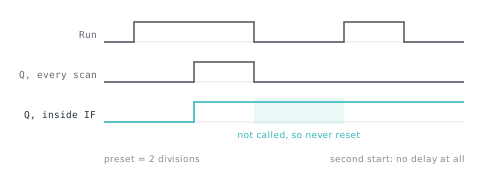
The fix is to call the instance unconditionally with the rung condition as IN, exactly as in the worked example. The same applies to counters, R_TRIG, and any other block with memory. The timer behaviour itself is covered in TON, TOF and RTO.
Rule 3: one edge, one instance
Every ONS has its own storage bit, and every R_TRIG instance remembers its own previous input. Share one between two signals and both break:
(* Wrong: one instance, two signals *)
Edge(CLK := Start_PB);
IF Edge.Q THEN Start_Count := Start_Count + 1; END_IF;
Edge(CLK := Reset_PB);
IF Edge.Q THEN Reset_Count := Reset_Count + 1; END_IF;
Hold Start_PB with Reset_PB released and the instance sees TRUE, then FALSE, then TRUE again on the next scan. It reports a rising edge every scan, and Start_Count climbs as long as the button is held. Give each edge its own instance, and call each instance once per scan.
There is a subtler difference on the first scan. Rockwell's ONS sets its storage bit during prescan specifically to prevent an invalid trigger on the first scan (1756-RM003). If the input is already true when the controller starts, a ladder ONS does not fire. Check what your target's R_TRIG does when it is first called with CLK already TRUE, and test it. More on edges in one-shot instructions.
Rule 4: keep rung order and every duplicate coil
Rungs execute top to bottom, so a rung reads what earlier rungs wrote this scan and what later rungs wrote last scan (the scan cycle has the detail). Statement order in ST must match rung order exactly, or those one-scan relationships change.
Duplicate coils need the same care. If rung 1 is XIC(A)OTE(X); and rung 5 is XIC(B)OTE(X);, then X equals B at the end of the scan, and rungs 2 to 4 see X equal to A. Merging them into X := A OR B; changes both, which is why a converter must not 'tidy' them.
Outputs in the middle of a rung are legal in Logix ladder. An OTE sets rung-condition-out to rung-condition-in (1756-RM003), so XIC(A)OTE(B)XIC(C)OTE(D); is two statements: B := A; and D := A AND C;.
Rule 5: brackets, and which button wins
The seal-in Motor := (Start_PB OR Motor) AND NOT Stop_PB; is stop-dominant: press both buttons and the motor stops. Rewriting it with IF and ELSIF can silently swap the priority:
(* Start now wins if both are pressed *)
IF Start_PB THEN
  Motor := TRUE;
ELSIF Stop_PB THEN
  Motor := FALSE;
END_IF;
That is a safety-relevant change made by a 'cleaner' rewrite. Keep the boolean form, or put the stop test first. Why the ladder form behaves as it does is covered in latching versus seal-in.
Rockwell's [:=], and what an OTE really does
Logix Structured Text has a second assignment, the non-retentive [:=]. The tag it writes is reset to zero each time the controller enters Run mode, and when an SFC step with automatic reset is left (1756-PM007). Rockwell's import/export manual lists data_bit [:=] BOOL_expression; as the ST form of OTE.
The reason is prescan. An OTE clears its bit during prescan, on the way into Run, so a plain := is not quite the same: it keeps whatever value the tag had. Neither form changes Rule 1. A [:=] inside an IF still only writes when the IF is true, and only clears on a mode change.
Rungs that do not convert cleanly
| Rung feature | What goes wrong | How to recognise it |
|---|---|---|
| MCR zone | MCR is not available in ST; while the zone is switched off, every instruction in it executes as if its rung were false (1756-RM003) | Outputs that should drop when the zone is off stay on |
| Output in mid-rung | Later conditions get ANDed into the wrong output | An output that needs more conditions than its ladder rung had |
| Branch inside a branch | Precedence errors, or legs flattened into one OR | A coil that turns on from a combination the ladder never allowed |
| ONS or OSR | Instance shared, missing, or first-scan behaviour differs | Counts per scan, double counts, a count at power-up |
| TON, TOF, CTU in an IF | The block is not called when the condition is false | No delay on the second start, a count that never resets |
| RTO | A plain IEC TON is not retentive | Accumulated time lost whenever the rung goes false |
| Duplicate coils | Merged into one OR | Intermediate rungs see a different value |
Converting with /convert, and checking any converter
LADX Convert reads a Studio 5000 .L5X export, PLCopen XML or Siemens SCL and writes IEC Structured Text, Siemens SCL, Rockwell neutral text or PLCopen XML. It reads the file in the browser. Timers and one-shots come out as declared instances, and the conversion report lists what did not translate: instructions it has no equivalent for, which are left for you to rewrite, branches nested inside branches, RTO read as TON, and routines in languages other than ladder, which are skipped. If your source is an L5X, what is inside an L5X explains the format it reads.
Treat its output, and any converter's, as a draft to verify. The method that works is the same for a tool, an AI or a colleague: run the original and the conversion against the same sequence of inputs and compare the outputs step by step. The ladder can run in the LADX ladder simulator, which keeps an output image, per-instruction edge memory and millisecond timers (it has no RTO); the ST runs in your target's simulator or on a test controller.
| Step | Inputs | Hold for | Expected |
|---|---|---|---|
| 1 | Pulse Start_PB | 1 scan | Motor on, Fan off |
| 2 | Nothing | 6 s | Fan on at 5 s |
| 3 | Stop_PB on | 1 scan | Motor off, Fan off at once |
| 4 | Start_PB and Stop_PB together | 1 s | Motor stays off |
| 5 | Start, run 3 s, stop, start again | 6 s | Fan waits the full 5 s again |
| 6 | Part_Eye held | 10 scans | Parts increases by 1, not 10 |
| 7 | Fault on, Ack_PB pressed | 1 scan | Alarm stays latched while Fault is on |
Each step targets one rule: 3 and 5 catch a timer inside an IF, 4 catches swapped priority, 6 catches a lost edge, 7 catches reordered latches. A conversion that passes all seven on this program has earned some trust; one that fails any of them has told you exactly where to look. For moves between vendors rather than languages, cross-vendor PLC migration covers the rest of the job.
Sources and further reading
- Rockwell Logix 5000 Structured Text Programming Manual (1756-PM007)literature.rockwellautomation.com
- Rockwell Logix 5000 General Instructions Reference (now 1756-RM018A): ONS, OSRI, TONR, MCRliterature.rockwellautomation.com
- CODESYS online help: ST statement IFcontent.helpme-codesys.com
- CODESYS Standard library: R_TRIGcontent.helpme-codesys.com
- PLCopen: XML exchange format for IEC 61131-3plcopen.org
Common questions
- What is the Structured Text equivalent of a one-shot in Studio 5000?
- In Logix Structured Text the rising-edge one-shot is OSRI, which works on a tag with InputBit and OutputBit members: set InputBit to the condition, call OSRI(tag), then test OutputBit. Rockwell's ST manual uses exactly this pattern. In IEC Structured Text, such as CODESYS, the equivalent is an R_TRIG instance.
- Should I convert working ladder logic to Structured Text at all?
- Only if there is a reason. Ladder suits interlocks and permissives that maintenance staff read online; Structured Text suits calculation, loops and string handling. A working routine rewritten for style gains nothing and carries new risk. Convert when moving platforms, when the logic is really arithmetic, or when the ladder has become unreadable.
- Can an AI tool convert ladder logic to Structured Text?
- It can produce a draft, and the same rules apply to that draft as to any converter. LADX Studio's assistant compiles and checks the code it generates before showing it, which catches syntax and type errors. It cannot know your process, so a timer moved inside an IF still needs a test sequence to find.
- Why does my converted Structured Text count ten parts instead of one?
- The edge was lost. In ladder, a one-shot or a counter only acts on the false-to-true transition of its rung. An ADD or assignment in Structured Text runs on every scan the condition is true, so a sensor held for ten scans adds ten. Put an R_TRIG on the input and act on its Q output.
- Is PLCopen XML a way to move ladder logic between vendors?
- It is the vendor-neutral exchange format: PLCopen's XML specification for IEC 61131-3, now at version 2.01, became IEC 61131-10 in 2019. Whether a given tool imports every part of a file is something to test rather than assume, so treat it like any other conversion and check the result in the target.
Keep reading
- Practice
PLC interview questions and answers: what interviewers listen for
Twenty-five PLC interview questions grouped by level, each with a model answer, the reasoning the interviewer is listening for, and the answer that loses marks.
- Languages
The five IEC 61131-3 languages, and when each is right
One standard, five notations. Most projects use two, and choosing badly makes a program nobody wants to maintain.
- Languages
Structured Text for people who think in ladder
The translation is mostly mechanical, and four constructs cover the majority of real code.