

Studio 5000 MSG instruction: path, setup and error codes
How to set up a Studio 5000 MSG instruction: message types, the communication path, connected and cached messages, and what each .ERR and .EXERR code means.
By the LADX engineering team
Short answer
The MSG instruction reads or writes a block of data in another device, asynchronously, starting when its rung goes from false to true. You choose a message type, source, length and destination, then a path of port and address pairs such as 1, 2, 2, 192.168.1.20, 1, 0. If it fails, .ER sets, .ERR holds the error code and .EXERR the extended code.
The MSG instruction is how one Logix controller reads or writes data in another device without the I/O tree doing it for you: another ControlLogix or CompactLogix, a PLC-5, an SLC 500 or MicroLogix, or a module's configuration. It is also where a lot of commissioning time goes, because the error codes are terse and the extended codes are not displayed at all.
Everything specific below comes from Rockwell: the Logix 5000 Controller Messages programming manual (1756-PM012), the general instructions reference that the 1756-RM003 link now serves as 1756-RM018A, and the Logix Designer online help.
What the MSG instruction does
MSG transfers a block of data asynchronously. The rung starts it; the transfer finishes some scans later while the program carries on. Rockwell calls it a transitional instruction: in ladder it executes when the rung goes from false to true, and in Structured Text you must condition it yourself so that it executes only on a transition.
Each MSG needs a control tag of type MESSAGE, and 1756-PM012 sets three rules for that tag: controller scope, not part of an array, and not part of a user-defined type.
Messages queue. An enabled MSG passes through a throttle with 16 positions into a message queue that holds 48. Enable more than 16 in the same moment and the rest wait, still enabled, until a position frees. Large polling programs therefore sequence their messages in groups rather than firing them all together; 1756-PM012 includes a message manager pattern for exactly that.
Choose the message type
| Target | Message types |
|---|---|
| Another Logix 5000 controller | CIP Data Table Read, CIP Data Table Write |
| An I/O module configured in Logix Designer | Module Reconfigure, CIP Generic |
| PLC-5 | PLC-5 Typed Read or Write, PLC-5 Word Range Read or Write |
| SLC 500 or MicroLogix | SLC Typed Read, SLC Typed Write |
| Block-transfer module | Block-Transfer Read, Block-Transfer Write |
With redundancy enabled on a ControlLogix 5580 or GuardLogix 5580, the PLC-5, SLC, MicroLogix, PLC-3, PLC-2 and block-transfer message types are not supported.
Source, destination and the rules that cause most errors
- Types must match. For CIP Data Table Read and Write, the online help says the source and destination types must match. A DINT array read into a REAL array fails.
- Base tags at the far end. Writing Logix to Logix, the destination in the remote controller must be a base tag, not an alias. Reading, the source in the remote controller must be a base tag. Aliases are fine on the local side.
- Scope. Tags referenced in the remote controller must be controller scoped. Locally, ControlLogix 5570 and CompactLogix 5370 families need controller-scope tags; 5380, 5580 and 5590 controllers at version 31 and later can also use program-scope tags.
- Not every type travels. Logix Designer's help says I/O structure tags and BOOLs are not supported for the source element; INT, DINT and the other data types can be used.
- Older controllers use their own addresses. For a PLC-5 or SLC, the remote element is written in that controller's syntax, such as
N7:10. Rockwell recommends a buffer of INTs for the message and DINTs everywhere else in the Logix project, with a FAL to convert. - Count elements, not bytes. For CIP and typed messages, an element is one element of the array you name as the source of a write or the destination of a read.
Build the communication path
The path is the route the message takes, written as pairs: a port to leave by, then the address on the far side of that port. The Logix Designer help gives the port numbers:
| Network | Port | Next address |
|---|---|---|
| Backplane | 1 | Slot number of the module |
| EtherNet/IP | 2 | IP address, IP:port, DNS name or DNS name:port |
| ControlNet | 2 | Node number, 1 to 99 decimal |
| DH+ channel A | 2 | 8# then the octal node, 1 to 77 octal |
| DH+ channel B | 3 | 8# then the octal node |
| DF1 serial | 2 for channel 0, 3 for channel 1 | Station address, 0 to 254 |
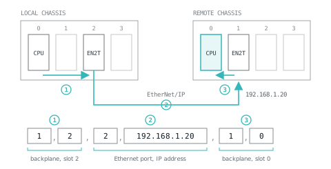
So to reach a controller in slot 0 of a remote chassis, through a 1756-EN2T in slot 2 of the local chassis and an Ethernet module at 192.168.1.20 in the remote one, the path is:
1, 2, 2, 192.168.1.20, 1, 0Read it in pairs: backplane to slot 2; out of that module's Ethernet port to 192.168.1.20; across the remote backplane to slot 0. Rockwell's own example path is 1, 0, 2, 42, 1, 3. The keyword THIS is a path to the controller itself, used for unconnected messages to the local controller.
You do not have to type paths. 1756-PM012 recommends, though does not require, adding the local communication module, the remote module and the remote controller to the I/O configuration, after which Browse picks the destination. If only the local module is in the I/O tree, browse to it and type the rest.
Logic can also change the path at run time through the MESSAGE tag's .Path member, entered as hexadecimal bytes without commas: the path 1, 0, 2, 42, 1, 3 becomes $01$00$02$2A$01$03.
Connected, unconnected and cached
| Message | Communication method | Uses a connection |
|---|---|---|
| CIP Data Table Read or Write | Any | Your option; Rockwell recommends connected for most applications |
| PLC-2, PLC-3, PLC-5 or SLC | CIP, or CIP with Source ID | No |
| PLC-2, PLC-3, PLC-5 or SLC | DH+ | Yes |
| CIP Generic | Any | Your option; Rockwell recommends unconnected unless you need Large Connection |
| Block-transfer read or write | Any | Yes |
A connected message can cache its connection, controlled by the .EN_CC bit, so the connection stays open after the message completes. Rockwell's guidance in 1756-PM012 is direct: for messages that execute at high frequency to the same device, configure them connected and cached. Firmware 12.x and later can cache up to 32 connections. Messages to the same device can share one cached connection when they are not enabled in the same scan.
Unconnected messages, and the first execution of a connected one, use an unconnected buffer. On CompactLogix 5370, ControlLogix 5570 and their GuardLogix equivalents there are 10 to 40 of these, 10 by default, each using 1.2 KB; if none is free when a message leaves the queue, it errors and no data moves. Rockwell suggests starting at the number of unconnected and uncached messages enabled at once, plus five.
Timeouts: an unconnected message, or the attempt to open a connection, errors if no response arrives within .UnconnectedTimeout, 30 seconds by default. Once connected, the timeout is ConnectionRate times the TimeoutMultiplier factor; the defaults, 7.5 seconds and a factor of 4, also give 30 seconds.
Status bits, and a trigger that does not jam
| Member | Meaning |
|---|---|
.EN | Enabled: set when the rung goes true, held until .DN or .ER is set and the rung is false |
.EW | Enable waiting: the request has entered the queue |
.ST | Started: the controller has begun executing it |
.DN | Done: the last packet transferred; reset at the next false-to-true |
.ER | Error: the transfer failed; reset at the next false-to-true |
.TO | Set it to abandon the message; the controller stops and sets .ER |
.EN_CC | Cache the connection |
.ERR, .EXERR | Error code and extended error code |
Never write .EN, .EW, .ST, .DN or .ER, directly or by clearing the .FLAGS word. Rockwell warns the controller may suffer a non-recoverable fault and clear the project from memory. If logic tests the status bits in more than one place, copy .FLAGS once and test the copy, because the bits can change partway through a scan.
A polling pattern in neutral text, with the interlock Rockwell recommends (an XIO of the MSG's own .EN in series):
XIO(Poll_Timer.DN)TON(Poll_Timer,1000,0);
XIC(Poll_Timer.DN)XIO(Read_Line2.EN)MSG(Read_Line2);
XIC(Read_Line2.DN)MOV(0,Read_Fails);
XIC(Read_Line2.ER)ONS(Read_Err_OS)ADD(Read_Fails,1,Read_Fails);
GEQ(Read_Fails,3)OTE(Line2_Comms_Lost);
The timer gives a one-scan pulse every second, and the XIO stops a slow message being retriggered before it finishes. Errors are counted rather than alarmed on the first one. In Structured Text the trigger is an IF: IF Poll_Timer.DN AND NOT Read_Line2.EN THEN MSG(Read_Line2); END_IF;. The pulse timer and the edge are covered in TON, TOF and RTO and one-shot instructions. The LADX ladder simulator has no MSG instruction, but the trigger, counter and watchdog rungs can be practised there with ordinary bits standing in for .DN and .ER.
MSG error codes (.ERR)
When .ER sets, .ERR holds a hexadecimal code. The meanings are Rockwell's, from 1756-RM003; the checks are where each one usually leads.
| .ERR | Rockwell's meaning | Check |
|---|---|---|
| 0001 | Connection failure (see extended code) | Path, the target's presence, then .EXERR |
| 0002 | Insufficient resource | Connections and buffers in use; cache, or sequence messages |
| 0003 | Invalid value | Message parameters, especially CIP Generic class, instance and attribute |
| 0004 | IOI syntax error (see extended code) | The remote tag name or address as typed |
| 0005 | Destination unknown, class unsupported, instance undefined or structure element undefined | The remote tag exists, is controller scoped and is spelt exactly |
| 0006 | Insufficient packet space | Element count; split the message |
| 0007 | Connection lost | Network, power or a reset at the target |
| 0008 | Service unsupported | Message type against what the target supports |
| 0009 | Error in data segment or invalid attribute value | Data or attribute value sent |
| 000F | Permission denied | Security and access settings at the target |
| 0010 | Device state conflict | The target's mode: Program, faulted, downloading |
| 0011 | Reply will not fit | Local destination too small for the data returned |
| 0013 | Insufficient command data | Element count and types |
| 0015 | Too much data | Element count against the remote tag size |
| 001F | Connection related failure (see extended code) | .EXERR, then path and target |
| 00D1 | Module not in run state | Target module status |
| 00FB to 00FE | Port not supported, unsupported data type, uninitialised, timeout | Path port numbers, data types, timeouts |
| 00FF | General error (see extended code) | .EXERR always |
Extended error codes (.EXERR)
Logix Designer shows no text for these, so read the number from the tag. They are grouped by the .ERR code they belong to.
| Under | .EXERR | Rockwell's meaning |
|---|---|---|
| 0001 | 0100 | Connection in use |
| 0001 | 0106 | Ownership conflict |
| 0001 | 0107 | Connection not found |
| 0001 | 0114, 0115, 0116 | Wrong module, wrong device type, wrong revision |
| 0001 | 011A | Application out of connections |
| 0001 | 0203 | Connection timeout |
| 0001 | 0204 | Unconnected message timeout |
| 0001 | 0205, 0206 | Unconnected send parameter error, message too large |
| 0001 | 0301, 0302 | No buffer memory, bandwidth not available |
| 0001 | 0311 | Port not available |
| 0001 | 0312 | Link address not available |
| 0001 | 0315 | Invalid segment type |
| 001F | 0203 | Connection timeout |
| 0004, 0005 | 0000, 0001 | Extended status out of memory, out of instances |
| 00FF | 2104, 2105 | Address out of range; address and how many out of range |
| 00FF | 2107 | Type is invalid or not supported |
| 00FF | 2108 | Controller in upload or download mode |
| 00FF | 210A, 210B | Invalid symbol name, symbol does not exist |
| 00FF | 2113, 2114 | Controller in faulted mode, Run mode inhibited |
Reading the ones that point at a specific mistake: 0204 under 0001 (nothing answered within the timeout: wrong IP, wrong slot, target off or unreachable); 0311 and 0312 (a port or address in the path that does not exist, often a slot number one out); 0315 (a malformed path); 2104 (asking for elements past the end of the remote array); 2107 (source and destination types differ).
PLC-5 and SLC error codes
Messages to PLC-5, SLC and MicroLogix controllers use PCCC, and from Logix firmware 10.x these errors get their own .ERR values, so .EXERR is no longer needed for them. Common ones: 1000 illegal command or format from the local processor; 3000 remote node missing, disconnected or shut down; 4000 processor connected but faulted; 7000 processor in Program mode; F006 address file does not exist in the target; F007 destination file too small for the number of words requested; F00B privilege error, access denied. The full table is in 1756-RM003.
A troubleshooting order
- Read .ERR, and .EXERR from the tag monitor, not from the dialog.
- Timeouts and 'not available' codes are path problems: check every port and address, ideally by browsing.
- 0004, 0005 and 210B are naming problems: remote tag spelling, existence and scope.
- 2104, 2107 and 0011 are size and type problems: compare both ends.
- 0002, 0301 and a queue that never empties are resource problems: cache frequent messages and sequence the rest.
A structured way of working through faults like these is in the PLC troubleshooting method. If the data is heading for a database rather than another controller, getting PLC data into a database compares the options that do not load the controller with messages. For network choices, see EtherNet/IP versus PROFINET, and if a path refuses to work, ask in the LADX forum with the path, the .ERR and the .EXERR.
Sources and further reading
- Rockwell Logix 5000 Controller Messages Programming Manual (1756-PM012)literature.rockwellautomation.com
- Rockwell Logix 5000 General Instructions Reference (now 1756-RM018A): MSG and its error codesliterature.rockwellautomation.com
- Studio 5000 Logix Designer online help: MESSAGE structurerockwellautomation.com
- Studio 5000 Logix Designer online help: Specify the communication detailsrockwellautomation.com
- Studio 5000 Logix Designer online help: MSG configuration examplesrockwellautomation.com
Common questions
- Should I use a read message or a write message between two controllers?
- Prefer reads where you can. Rockwell's guidelines in 1756-PM012 say read messages make troubleshooting simpler, because the controller that uses the data is the one that fetches it and its configuration is visible there. A write changes data in another controller, and finding where a value came from then depends on how well the code is commented.
- Can a MSG instruction read a program-scope tag?
- In the remote controller, no: Rockwell says tags referenced in the remote controller must be controller scoped. In the controller running the MSG, it depends on the family. ControlLogix 5570 and CompactLogix 5370 controllers need controller scope; 5380, 5580 and 5590 controllers at version 31 or later can also use program-scope tags.
- Why does Studio 5000 show no description for my .EXERR code?
- Rockwell states that Logix Designer does not display any text for extended error codes. Read the number from the .EXERR member in the tag monitor and look it up against the error code it belongs to: the same extended number means different things under 0001, 001F and 00FF.
- How many MSG instructions can run at once?
- The controller passes enabled messages through a throttle of 16 positions into a queue that holds 48. A 17th message enabled at the same moment waits, with .EN set and .EW clear, until a position frees. Rockwell recommends sequencing or grouping messages when more than 16 might be enabled together.
Keep reading
- Practice
ControlLogix major fault codes: Type 4 Code 20 and the rest
What the common ControlLogix and CompactLogix major fault types and codes mean, how to find what caused one, and how to clear it without hiding the next one.
- Networking
EtherNet/IP and PROFINET: same cable, different worlds
Both run on Ethernet and neither talks to the other, which is a fact of purchasing more than of engineering.
- Migration
L5X file: what it is and how to open, edit or convert one
An L5X is Studio 5000's XML export. What is inside it, how it differs from L5K and ACD, and how to open, import, hand-edit or convert one safely.